Page 30
Chapter 8 Pin Assignment and Specification
8.1 Pin Assignments
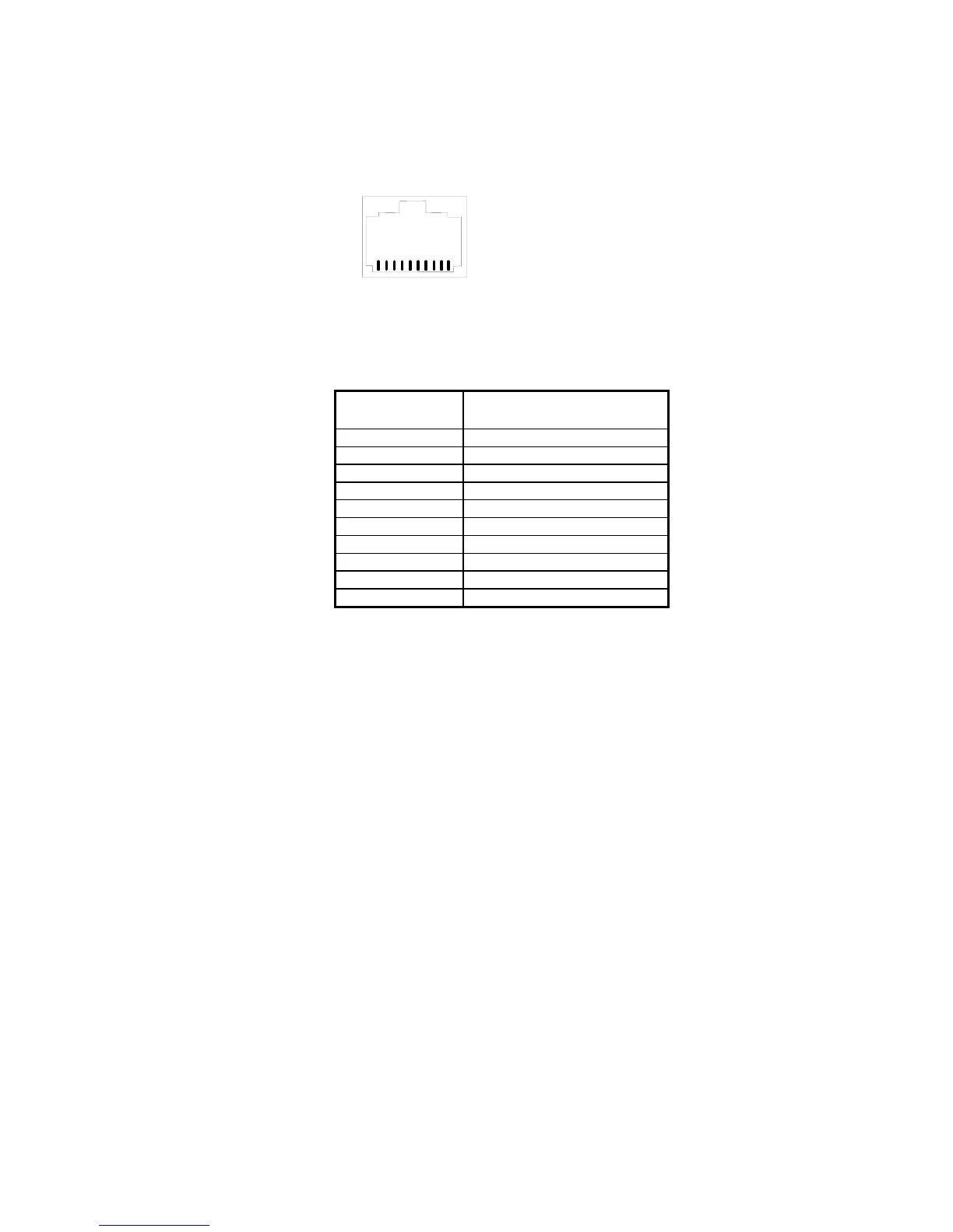
The modular connector
located at the bottom of
the scanner handle has
the pin numbering as
shown at the right
picture
8.1.1. Keyboard Interface
The next table shows the modular connector pinout for keyboard
interface:
Pin
Number
Signal
1 Not Used
2 VCC (+5V, output)
3 DET
4 GND
5 Terminal Data
6 Terminal Clock
7 Power Input (+5V)
8 Keyboard Clock
9 Keyboard Data
10 Not Used
Note: DET signal is bi-directional I/O pin and for internal use only.
As keyboard interface, there are two other connectors on the interface
cable. The connector type and pinout differ from terminal to terminal
and are not listed here.
8.1.2. RS232 Interface
The scanner supports TTL RS232 at modular connector and standard
RS232 after the interface cable is attached.
1
10
Modular Connector ( Front View)