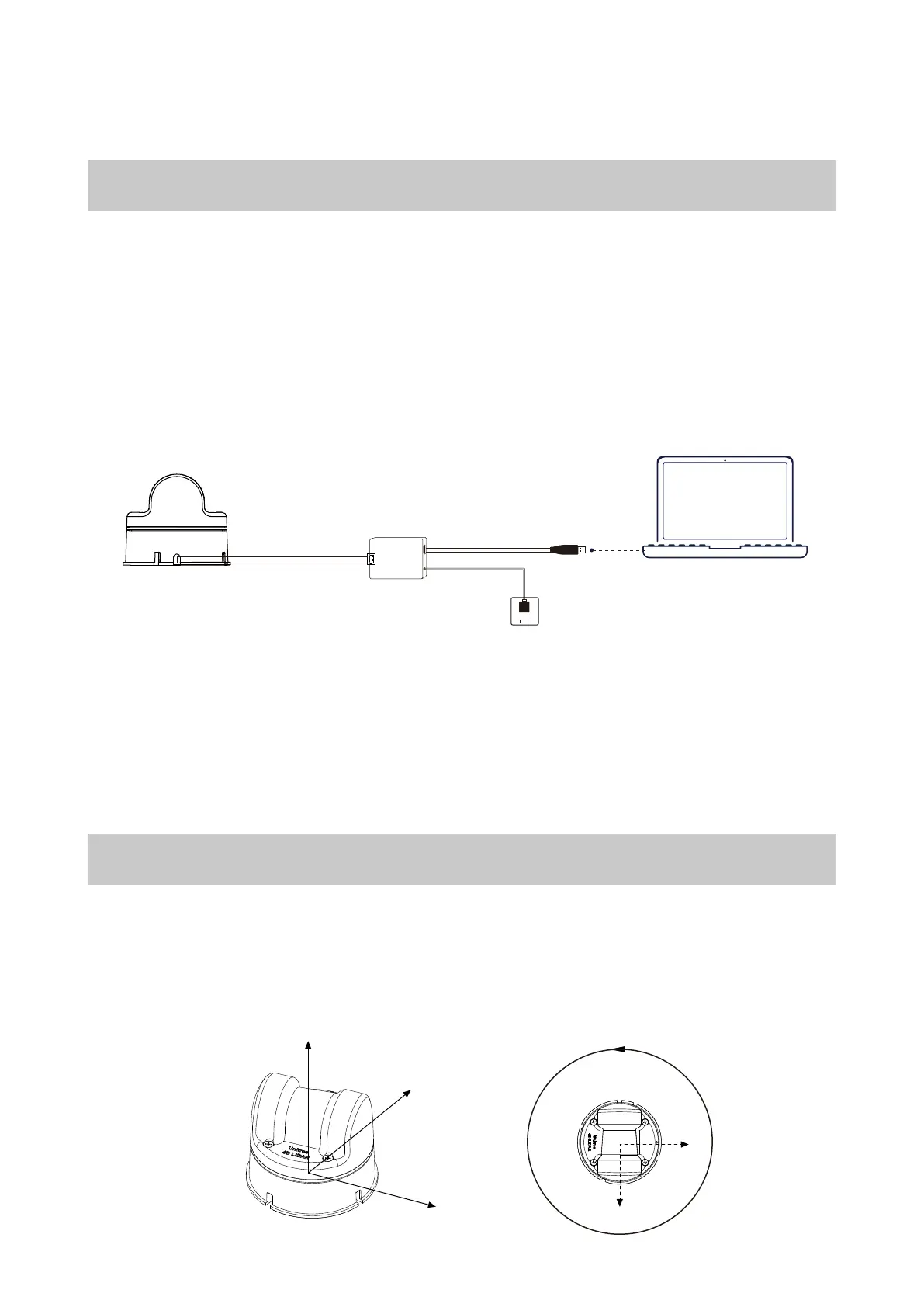
Coordinate System
TheCartesian coordinate systemof L1, denoted as 0-XYZ, is defined as shown in the diagram below. O
is the origin of thepoint cloud coordinatesystem, located at the bottom center position, with the +X
axis pointing in the opposite direction of the outlet, and the +Y axis pointing counterclockwise 90 ° from
the +X axis. O-XYZ is thepoint cloud coordinate systemof L1(The origin andXYZ coordinate systemof
the IMU can be found in theL1 3D model, and itsXYZ axesare parallel to thepoint cloud coordinate
system.)
Usage
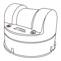
Wiring
The 4-pin connector of the L1 provides external power and data transmission. Please refer to the
Interface Definition section for the specific pinouts. To temporarily test or use the L1, we recommend
using the included adapter module, power adapter, and data cable for connection and usage as fol-
lows:
a. Insert the 4-pin serial port of the L1 into the adapter module.
b. Insert the power adapter into the power port of the adapter module for power supply.
c. Insert the Type-C interface of the data cable into the data communication port of the adapter
module and connect the other end to a personal computer.
The adapter module, power adapter, and data cable are included in the package and can be used
for power supply, control signal transmission, and data transmission. Alternatively, you can use
other cables according to your needs to improve usability and system protection (such as dust and
waterproofing).
When debugging, be sure to place the L1 radar on the included rubber pad and place the rubber
pad on a flat surface to ensure stable operation and prevent collisions and falls.
9
Unitree 4D LiDAR-L1 Coordinate Definition
Unitree4D LiDAR-L1 Adapter Module
Connecting to an External Power Source
USB to Type-C Cable
Unitree
O
Z
X
Y
360°
X
Y