Unitronics’s BACnet Gateway User Guide Page 4 of 28
Unitronics
LIST OF FIGURES
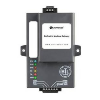
Figure 1: BACnet board ....................................................................................................................................................... 6
Figure 2: Power and RS-485 Connections ........................................................................................................................... 7
Figure 3: Modbus RS-485 Biasing Switch on the GW-BAC1 .............................................................................................. 8
Figure 4: Modbus RS-485 End-Of-Line Termination Switch on the GW-BAC1 ................................................................... 9
Figure 5: Connection from GW-BAC1 to RS-485 Field Network ....................................................................................... 10
Figure 6: RS-485 EOL Switch ............................................................................................................................................. 10
Figure 7: Required current draw for the GW-BAC1 .......................................................................................................... 11
Figure 8: Power Connections ............................................................................................................................................ 11
Figure 9: Tools menu on VisiLogic .................................................................................................................................... 12
Figure 10: Tools menu on UniLogic .................................................................................................................................. 12
Figure 11: BACnet Connection MS/TP Screen .................................................................................................................. 13
Figure 12: BACnet Connection IP Screen .......................................................................................................................... 13
Figure 13: BACnet Nodes Screen ..................................................................................................................................... 14
Figure 14: BACnet Map descriptors Screen ...................................................................................................................... 14
Figure 15: Modbus connection RTU Screen ..................................................................................................................... 15
Figure 16: Modbus connection IP Screen ......................................................................................................................... 15
Figure 17: Finish Screen .................................................................................................................................................... 16
Figure 18: File Transfer Screen ......................................................................................................................................... 17
Figure 19: File menu ......................................................................................................................................................... 17
Figure 20: MODBUS RTU configuration ............................................................................................................................ 18
Figure 21: Example of COM initialize ................................................................................................................................ 18
Figure 22: Example of Modbus configuration .................................................................................................................. 19
Figure 23: Example of MODBUS TCP/IP configurator ....................................................................................................... 19
Figure 24: Example of TCP/IP card and socket initialize ................................................................................................... 19
Figure 25: Example of TCP/IP card and socket initialize ................................................................................................... 20
Figure 26: Example of MODBUS Command ...................................................................................................................... 20
Figure 27: Ethernet Port Location..................................................................................................................................... 21
Figure 28: PC IP configuration .......................................................................................................................................... 21
Figure 29: Changing IP Address via FST Web GUI ............................................................................................................. 22
Figure 30: Ethernet Port Location..................................................................................................................................... 24
Figure 31: Diagnostic tool – device selection ................................................................................................................... 24
Figure 32: Diagnostic selection ......................................................................................................................................... 25
Figure 33: Diagnostic tool – start diagnostic .................................................................................................................... 25
Figure 34: Diagnostic tool –diagnostic test complete ...................................................................................................... 26
Figure 35: Diagnostic LEDs ................................................................................................................................................ 27
Figure 36: Specifications ................................................................................................................................................... 28