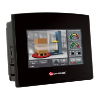
Vision™ OPLC™, V1040-T20B
Removable
Memory Storage
Micro-SD card: store datalogs, Alarms, Trends,
Data Tables; export to Excel;
backup Ladder, HMI & OS and use this data to ‘clone’ PLCs.
For more data, refer to the SD
topics in the VisiLogic Help system.
Data Tables
Data tables enable you to set recipe parameters and create datalogs.
Additional product documentation is in the Technical Library, located at
Technical support is available at the site, and from support@unitronics.com.
Standard Kit Contents
Vision controller USB programming cable
3 pin power supply connector Mounting brackets (x8)
5 pin CANbus connector Rubber seal
CANbus network termination resistor Unitronics’ Setup CD
Battery (not installed)
Danger Symbols
When any of the
following symbols appear, read the associated information carefully.
Symbol Meaning Description
Danger
The identified danger causes physical and property damage.
Warning
The identified danger could cause physical and property damage.
Caution Caution Use caution.
Before using this product, the user must read and understand this document.
All examples and diagrams are intended to aid understanding,
and do not guarantee operation.
Unitronics accepts no responsibility for actual use of this prod
uct based on these examples.
Please dispose of this product according to local and national standards and regulations.
Only qualified service personnel shou
ld open this device or carry out repairs.
Failure to comply with appropriate safety guidelines
can cause severe injury or property damage.
Do not attempt to use this device with parameters that exceed permissible levels.
To avoid damaging the system, do not connect/disconnect the device when power is on.
Environmental Considerations
Do not install in areas with: excessive or conductive dust, corrosive or flammable gas,
moisture or rain, excessive heat, regular impact shocks or excessive vibration, in accordance
with the standards given in the product’s technical specification sheet.
Ventilation: 10mm space required between controller’s top/bottom edges & enclosure walls.
Do not place in water or let water leak onto the unit.
Do not allow debris to fall inside the unit during installation.
Install at maximum distance from high-volta
ge cables and power equipment.
Installation Guide
Unitronics
.
-B)
njury or property damage.
e vibration, in accordance

 Loading...