Installation Guide
Unitronics
Wiring
Do not touch live wires.
Install an external circuit breaker. Guard against short-
circuiting in external wiring.
Use appropriate circuit protection devices.
Unused pins should not be connected. Ignoring this directive may damage the device.
Double-check all wiring before turning on the power supply.
Caution
To avoid
damaging the wire, do not exceed a maximum torque of 0.5
Do not use tin, solder, or any substance on stripped wire that might cause the wire
strand to break.
Install at maximum distance from high-
voltage cables and power equipment.
Wiring Procedure
Use crimp terminals for wiring; use 26-12 AWG wire (0.13 mm
2
–3.31 mm
2
).
1. Strip the wire to a length of 7±0.5mm (0.250–0.300 inches).
2. Unscrew the terminal to its widest position before inserting a wire.
3. Insert the wire completely into the terminal to ensure a proper connection.
4. Tighten enough to keep the wire from pulling free.
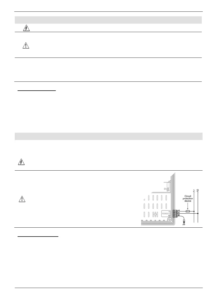
Power Supply
The controller V1040-T20B requires e
ither an external 12 or 24VDC power supply.
Permissible input voltage range: 10.2-28.8VDC, with less than 10% ripple.
The power supply
must include double insulation. Outputs must be rated as
SELV/PELV/Class 2/Limited Power.
Do not connect either the ‘Neutral or ‘Line’ signal of the
110/220VAC to device’s 0V pin.
Install an external circuit breaker. Guard against short-
circuiting in external wiring.
Double-check all wiring before turning on the power
supply.
In the event of voltage fluctuations or non-conformity to
voltage power supply specifications, connect the device
to a regulated power supply.
Earthing the OPLC
To maximize system performance, avoid electromagnetic interference by:
Mounting the controller on a metal panel.
Connect the functional earth terminal of the OPLC, and the
I/Os, directly to the earth ground of your system.
For ground wiring, use the shortest and thickest possible wire.
, V1040-T20B
5
N·m (5 kgf·cm).
lines of
 Loading...