ACCESSORIES
Section 8-4
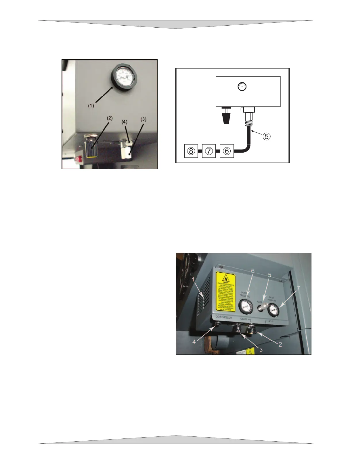
Making the Connections
Standard Air Assist style
In the left rear part of the system you will find the pressure gauge (1), flow adjustment valve (2), quick
release coupling (3), and release lever (4).
Push in the release lever and pull down on the quick release coupling to remove it from the machine.
Attach your compressed air supply hose to this fitting (1/4 NPT threads) and use Teflon tape on the
threads to prevent leaks. Re-insert the fitting until it “clicks” into place.
Attach the other end of the supply line (5) to a particulate filter (6), desiccant/dryer (7), and then to an oil-
free compressed air source (8).
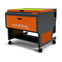
Computer Controlled Air Assist style
In the left rear part of the system you will find the
Air Assist control box. Attached to the box (not
shown in picture) there should be two special
quick release couplings secured with plastic tie
wraps (1). Using a pair of scissors or wire cutters,
cut off the plastic tie wraps and discard.
The AIR IN (2) fitting is where you attach the
compressed air supply. The GAS IN (3) fitting is
where you would attach an inert gas supply
(optional). If you purchased the optional Air
Compressor, you would connect the control wire to
the COMPRESSOR (4) connector (refer to the Air
Compressor instructions for more details). The
FLOW knob (5) is used to adjust airflow to the
work piece (through the cone) during operation.
You can monitor the pressure by observing the pressure gauges (6 & 7) during operation.