ACCESSORIES
Section 8-5
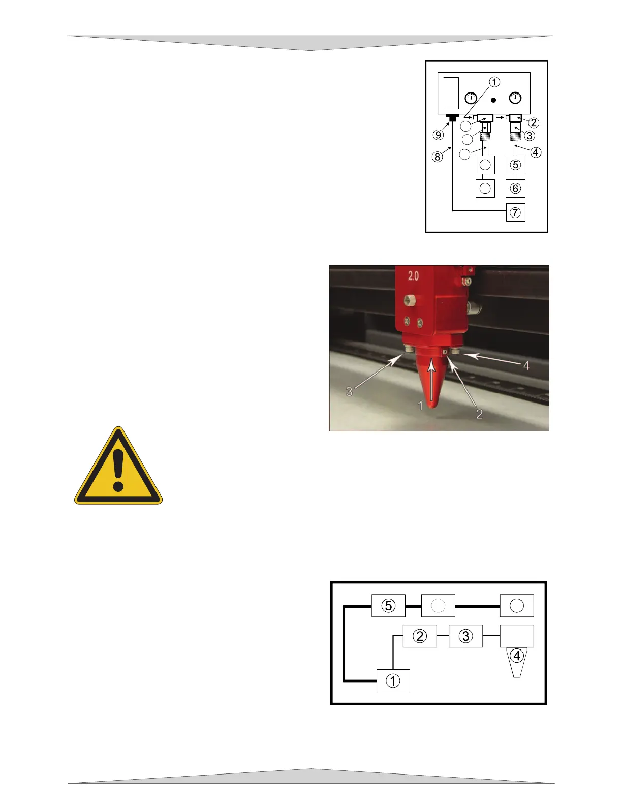
Locate the locking lever (1) attached to both fittings. Push in the lever until
it clicks. Attach the larger quick release coupling (3) (1/4 NPT threads) to
your compressed air supply line (4). Use Teflon tape on the threads to
prevent leaks. Push the quick release coupling (3) into the fitting (2) until it
clicks into place. Attach the other end of the supply line (4) to a particulate
filter (5), desiccant/dryer (6), and then to an oil-free compressed air source
(7). If you have purchased the optional Air Compressor, connect the control
wire (8) from the compressor (7) to the COMPRESSOR connector (9). If
using an inert gas, attach the smaller quick release coupling (11) (1/4 NPT
threads) to the supply line (12) using thread sealant or Teflon tape. Push
the quick release coupling (11) into the fitting (10) until it clicks into place.
Attach the other end of the supply line (12) to an external pressure regulator
(13) and then on to the gas tank (14).
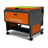
Cone Installation and Removal (both styles)
The cone must be attached to direct the air or gas
supply to the laser beam's focus point. To install the
cone, insert the cone (1) into the cone base completely
until it bottoms out. Using a .050 inch Allen wrench,
tighten the setscrew on the side of the cone base (2)
until it is snug. Re-check to make sure that the cone is
all the way into the base and is not tilted. To remove
the cone, simply loosen the setscrew (2) and pull the
cone straight down. DO NOT remove or loosen the
cone base mounting screws (3) & (4) to mount or
dismount the cone. These screws keep the cone base
aligned with the laser beam.
DO NOT install the cone unless you plan on using Air Assist. Leaving the cone
attached to the cone base and running the laser system without either air or gas
flowing through the cone will destroy the focus lens within a few minutes. If you are
not using Air Assist, REMOVE THE CONE. Damage of this nature is due to
neglect and WILL NOT be covered under warranty.
How it Works
Standard Air Assist
The Quick Release Fitting (1) is the entry point into the
rear enclosure of the laser system. From there, the air
lines branch off into two paths, the optics protection
path and the cone path. The optics protection path is
a direct path from the quick release fitting (1) to the
beam window (5), the #2 mirror (6), and the #3 mirror
(7). Since this is a direct path, the amount of air
pressure and flow that is coming from your
compressed air source will be applied to the optics to
help keep them clean from flying debris. The cone
path goes through the adjustment valve (2), to the
gauge (3), and then to the cone (4). The amount of air, flowing through the cone, is adjusted using the
adjustment valve (2) and monitoring the pressure displayed on the gauge (3). The cone path protects the
focus lens and provides a downward flow directly into the beam path at the focus point.
11
12
13
14
10
6 7