ACCESSORIES
Section 8-6
NOTE: Air will always be flowing through the system as long as the compressed air source is
turned ON. We recommend installing a shut off valve in between your compressed air supply and
the laser system.
Before you run your material, we suggest that you adjust your air and/or gas flow. To do this, you must
first turn on your compressed air source so that there is flow through the system. Now, either turn the
laser system ON or leave it OFF.
With the top door of the laser system open, pass a piece of paper underneath the cone and use it to note
the amount of air flowing through the cone and against the paper or place your finger underneath the
cone to try to feel the pressure.
As a safety precaution, you should place your finger underneath the cone
ONLY when power to the system has been turned OFF. If the power is ON,
you should use the paper method.
Turn the adjustment valve knob clockwise or counterclockwise until either the desired airflow or PSI
reading on the gauge is achieved. Clockwise adjustments reduce flow while counterclockwise
adjustments increase flow.
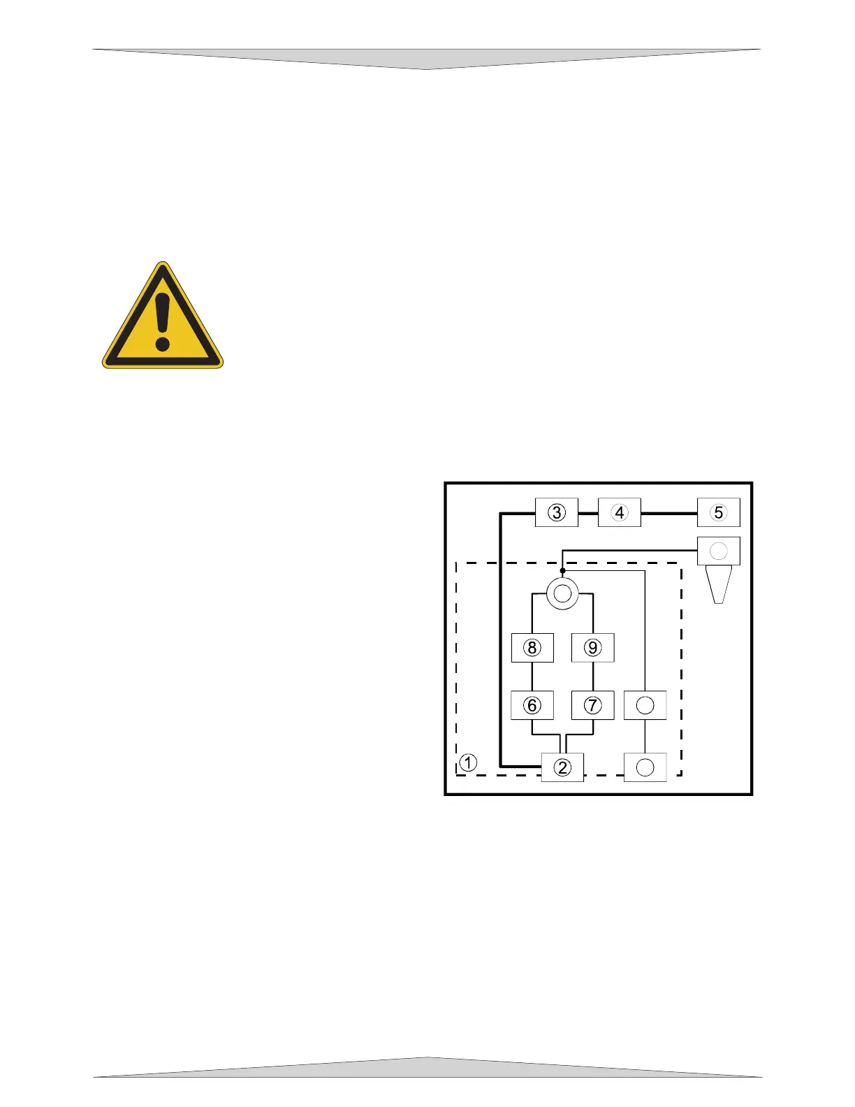
Computer Controlled Air Assist
The control box (1) (represented by the dotted lines)
directs the compressed air source to the optics
protection path and also to the cone. The optics
protection path is a direct path from the entry point of
the compressed air source (2) to the beam window
(3), the #2 mirror (4), and #3 mirror (5). The air
supply for the cone comes from either the HIGH (6)
or LOW (7) solenoid valves, through the HIGH (8) or
LOW (9) pressure adjustment valves, through the
pressure gauge (10) and finally to the cone. The
cone path protects the focus lens (11) and provides
a downward flow directly into the beam path at the
focus point. You choose which solenoid valve (6 or
7) to open through the laser systems printer driver.
The gauge (10) will ONLY show a reading when
either the HIGH (6) or LOW (7) solenoid valve is
opened and air is flowing to the cone. If you choose
to use an inert gas to supply the cone, the supply
must go through the GAS coupling (12), through the
gas solenoid valve (13) and finally to the cone. The
GAS path bypasses the pressure adjustment valves
and the gauge so it must be regulated externally. Only one solenoid valve (6, 7, or 13) can operate at
one time.
As the diagram indicates, the optics protection path is neither regulated nor solenoid valve controlled. If
you are using your own compressor, the optics protection air will always be flowing regardless of whether
the laser system is running or not. You must install either a manual shut off valve (not supplied) or an
external electronic solenoid valve system (not supplied). If you purchased the Air Compressor option the
optics protection air will turn ON and OFF as the compressor turns ON and OFF respectively.
When you press the “Start” button on the laser system, the Air Assist control box will send out a +5 VDC
signal through the COMPRESSOR control wire, which can be used to turn ON the Air Compressor
(optional) and will keep the Air Compressor ON until the file completes. This type of control saves
electricity, reduces the running time of the compressor, and reduces ambient noise when the laser
system is not running.
11
10
12
13