5.4. Robot Connection
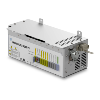
The robot arm connector, illustrated below, is next to the power supply connector. For details on
connecting the robot arm cable, refer to the Universal Robots User Manual.
1 Robot arm connector 2 OEM CB connector
3 Robot arm connector (e-Series) 4 OEMCBconnector (e-Series)
5.5. Circuit Breaker Installation
Use a double pole circuit breaker to protect the power input connector, as it can also be used as a
switch. If a fuse is used, then a two-pole switch must be installed between the fuse and power input
connector.
Installation Guide OEM Control Box
Copyright © 2019–2024 by UniversalRobotsA/S. All rights reserved.

 Loading...


