MSC-400 Reference Manual
Rev 4
27
Program Menu Step #2 - Devices & Routing
This section will assign each device to a dedicated IR output on the MSC-400. When assigned, the MSC-
400 will ONLY send a Connected Device’s IR Commands to the IR PORT ASSIGNED. This gives much
more precise control over the IR level delivered to the component and enables you to control identical
components. There is an option to send a device’s IR commands to ALL Ports for troubleshooting
purposes, however this should be avoided since all the emitters will be flooding the equipment location
with IR, reducing reliability.
TIP - In the example system, AVR (A/V Receiver), Tuner 1 and Tuner 2 are all assigned Port 1. This
particular receiver has two internal tuners and in the system configuration the tuners have been
setup as sources to be directly selected in Listen, but the IR commands for the tuners must be
directed to the AVR, Port 1.
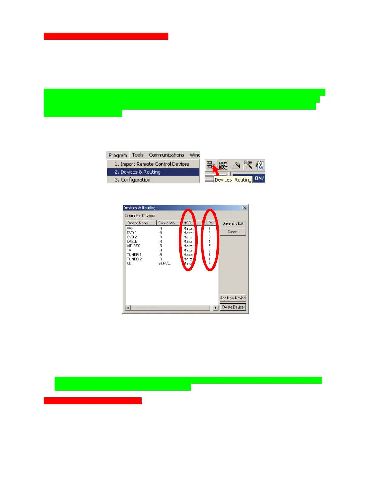
To open the DEVICES & ROUTING WINDOW, do either of:
a) In the MSC EDITOR MENU BAR, click PROGRAM, then click DEVICES & ROUTING.
b) In the MSC EDITOR TOOL BAR, click the DEVICES & ROUTING ICON.
The DEVICES & ROUTING WINDOW will appear.
Devices & Routing Window
1. The DEVICE NAME and CONTROL VIA columns are NOT CONFIGURABLE in this window.
2. All CONNECTED DEVICES will default to MASTER. Select MASTER/SLAVE as appropriate, from
the PULL-DOWN.
3. All CONNECTED DEVICES will default to PORT 1. Under PORT #, click ‘1’ and select the
appropriate PORT from the PULL-DOWN.
NOTE - In a Master/Slave System, each MSC-400 can only control eleven Connected Devices.
Port 12 is used as a Smart Macro Control Buss.
Optional Step - Adding IR Devices
Normally, you don’t need to add any devices, since you have already imported them from the remote
control. Use this step should you need to control an IR device that is needed for macros but not needed
on the remote control for the end user (for example a matrix video switcher).
2 3