© UPLIFT Desk • 800-349-3839 • 512-614-3152 • info@upliftdesk.com • upliftdesk.com
12
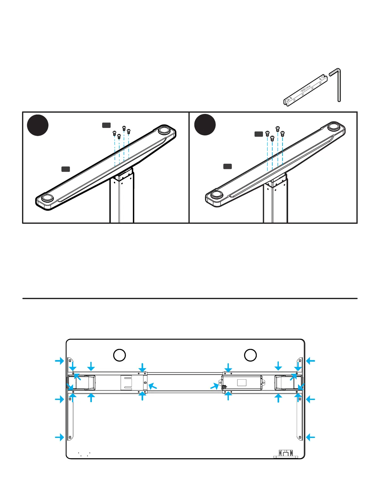
IMPORTANT!: Take this moment to double check that all of the screws indicated with arrows are tight. This
is an important step and it is much easier to ensure they are tight now before ipping the desk upright.
Don’t forget to check the Feet screws and the screw located underneath the Control Box on C-Frames.
Step 12 - Caster Installation (Optional)
If you purchased Casters for your desk, we recommend installing them now.
A. First, remove the pre-installed Leveling Glides from the Feet by rotating them counterclockwise to
unthread them from the mounting holes.
B. Install a Caster in each of the Leveling Glide holes by turning the stem of the Caster clockwise, threading
it into the hole. Use a 12mm or 1/2” at wrench to tighten Casters that include a hex nut on the threaded
stem for tightening.
Step 11 - Feet Attachment
A. Place one of the Feet (P1) on top of one of the Legs as shown. Note: If you are assembling a C-Frame,
make sure the long end of the Foot is facing towards the front of the desk in the same direction as the
long ends of the Side Brackets.
B. Loosely start four M6x14 Machine Screws (H2) through the Foot and into the end of the Leg, but don’t
tighten the screws yet.
C. Once all four screws have been started, tighten them using the 4mm Allen
Wrench and Allen Wrench Handle. It’s very important to the stability of the
desk that these screws are tight.
D. Repeat the previous steps to attach the second Foot.
H2
H2
P1
P1