© UPLIFT Desk • 800-349-3839 • 512-614-3152 • info@upliftdesk.com • upliftdesk.com
11
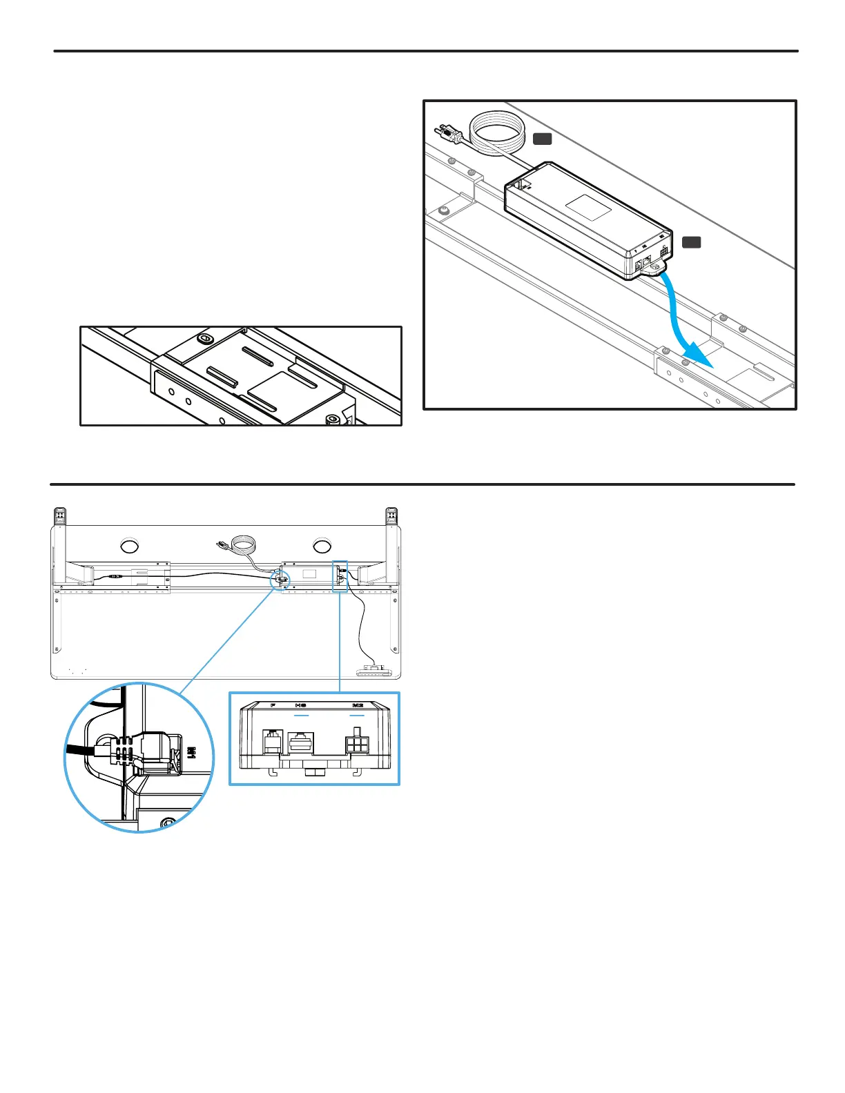
Step 10 - Cable Connections
A. Connect the cable of the Keypad (P8) into the
Control Box (P7) port labeled “HS”.
B. Connect the short cable of the Leg closest to the
Control Box directly into the white port of the
Control Box marked “M2”. This port is located on
the same end as the Keypad port marked “HS”.
C. Connect the short cable of the other Leg into the
Leg Cable Extension (P10). Be sure to connect
the short Leg cable to the “straight” connector
end of the Leg Cable Extension. Do NOT attempt
to connect the short Leg cable to the “angled”
connector end of the Leg Cable Extension.
D. IMPORTANT: Referring to Fig. 1, connect the
“angled” end of the Leg Cable Extension (P10)
into the white port marked “M1” located on top of
the Control Box with the cable pointing away from
the Control Box. Do not attempt to connect the
Leg Cable Extension with the cable running over
the top of the Control Box. Doing so will damage
the Leg Cable Extension and the Control Box.
Fig. 1
Top view of Control Box tabs & Crossbar End slot. This is just
an illustration, you won’t be able to see this when installing.
P9
P7
Step 9 - Control Box Attachment
A. Connect the Power Cable (P9) into the port on
the Control Box (P7) marked “AC”.
B. Position the Control Box near the Leg on the
side of the desk you have attached your Keypad
and point the Power Cable end away from the
Leg.
C. Slide the Control Box onto the Crossbar End
so that the tabs on the bottom of the Control
Box interlock with the slots in the Crossbar End
(P5) as shown. Note: The Control Box must be
attached to the frame for the desk to function
properly.