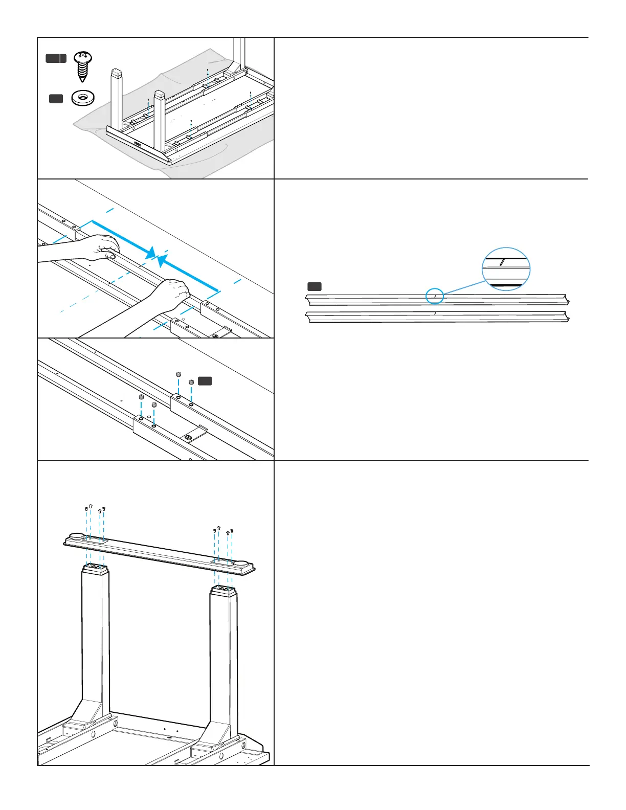
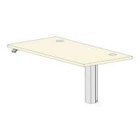
Step 11 - Crossbar Rail Positioning
A. Slide each Crossbar Rail (P3) left or right until the center
indicator mark is located approximately in the middle of the
Crossbar Ends (P2).
Step 10 - Crossbar End Attachment
A. Using a Phillips Head Screwdriver, loosely insert one #10x3/4”
Wood Screw (H4a) and one Washer (H5) through each Crossbar
End and into the desktop as shown.
B. Once all four screws are started, tighten them but be careful to
not overtighten to avoid stripping.
H3
B. Insert four M8x8 Set Screws (H3) into the holes in each
Crossbar End and tighten using the 4 mm Allen Wrench (H6).
P3
Center indicator marks
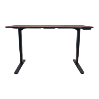
Step 12 - Foot Attachment
A. Place a Foot (P11) on top of the two legs (P1) on one side of the
desk with the pre-installed leveling glides facing up as shown.
B. Loosely insert eight M6x14 Machine Screws (H2) through the
holes in the Foot and into the eight threaded holes in the ends
of the two legs.
C. Once all eight screws have been started, tighten them with the
4 mm Allen Wrench.
D. Repeat the previous steps for the second Foot.
E. Do one nal tightening of all foot screws. Tight foot screws add
signicant stability.
C3
C4 C5
C9
H4a
H7
C6
H1 H2 H3
H5
H4b
H6
C7
C3
C4 C5
C9
H4a
H7
C6
H1 H2 H3
H5
H4b
H6
C7
H5
H4 a