Section 4 - Schematics Hydraulic
113101-000 MX15 / MX19 | Service Manual Page 4-11
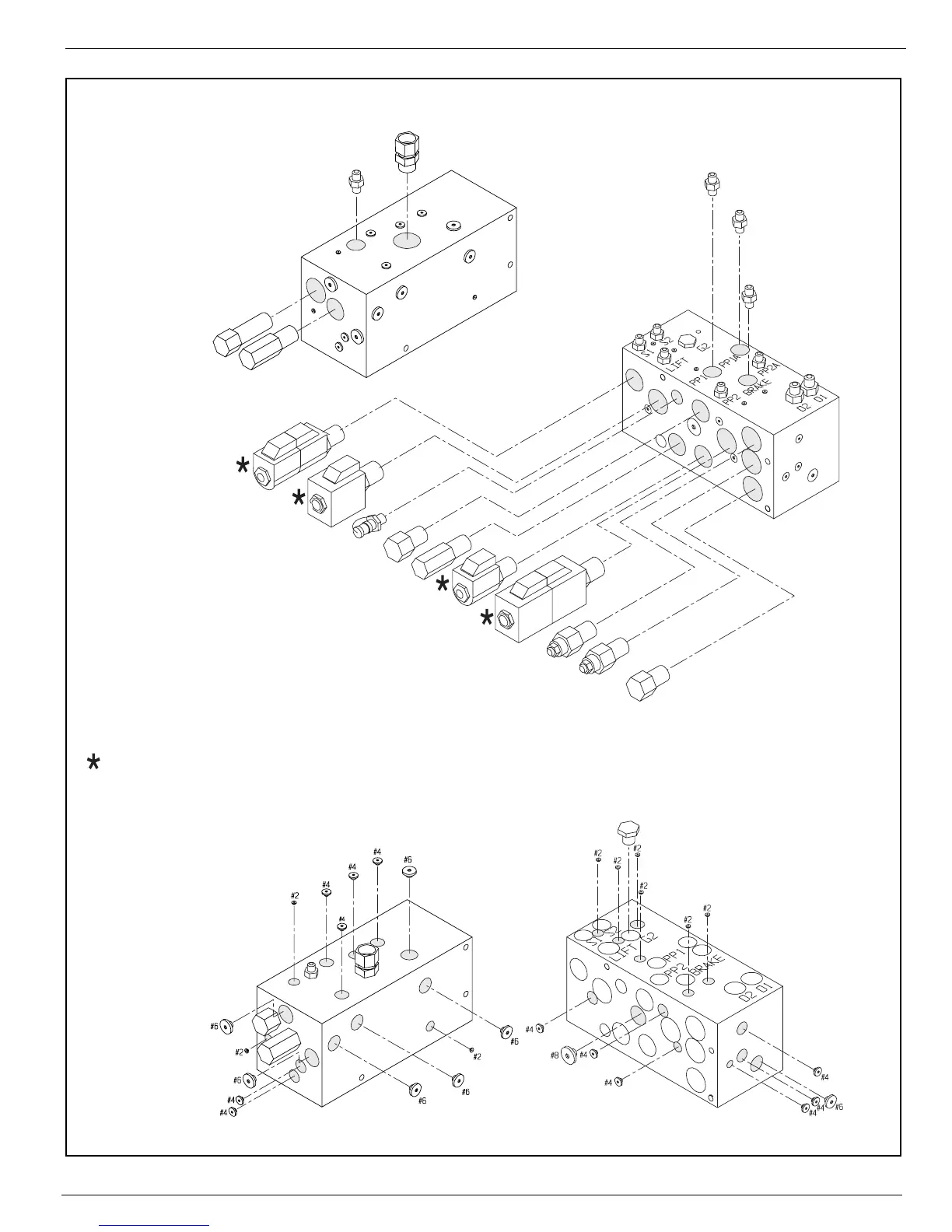
Figure 4-10:
Valve Diagram
Counterbalance Valve --
V5
Counterbalance Valve --
V5
Drive Solenoid and Valve
SOL4A, SOL4B, V4
Depression Mechanism Solenoid and Valve
SOL3A, V3A
Main Relief Valve --
RV3
Check Valve --
CV
Lift Solenoid and Valve
Sol2A, V2A
Steering Solenoid and Valve
Sol1A, Sol1B, V1
OR2 -- Depression Cylinder
.031 Orifice Fitting
OR2 -- Depression Cylinder
.031 Orifice Fitting
OR3 -- Brake
.031Orifice Fitting
High Pressure Test Port
Lift Relief Valve --
RV2
Front
Bottom
Right
Left
Rear
To p
(Mounting Surface)
To p
(Mounting Surface)
To p
(Mounting Surface)
To p
(Mounting Surface
Flow Divider Valve --
DVDR
Steering Relief Valve --
RV1
Pressure Port
Return Port
Front
Bottom
Right
Rear
Left
#2 Plug #2
#4 Plug #4
#6 Plug #6
#8 Plug #8
Coil oriented with spades away from work ports