Section 2 - Service and Repair Switch Adjustments
113101-000 MX15 / MX19 | Service Manual Page 2-13
C
HASSIS
C
ONTROLS
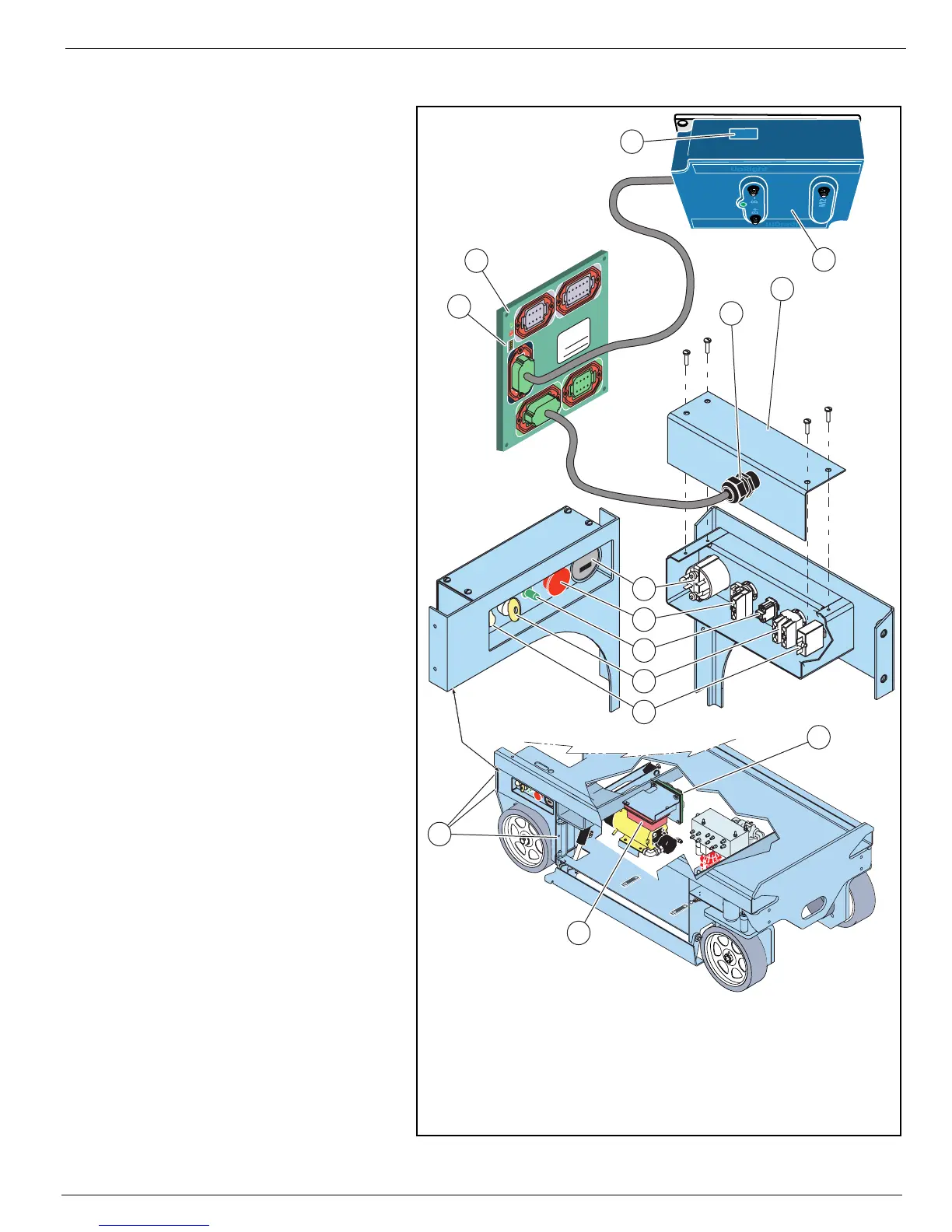
Figure 2-8:
Chassis Controls
Refer to
Section 4 - Schematics
for wiring diagrams.
Refer to the
Parts Manual
for
replacement part numbers.
To access the switches and com-
ponents for repair or replace-
ment;
1. Disconnect the cable from J4
on the I/O board.
2. Remove three capscrews and
nuts to remove the controller/
wheel cover assembly, and
take the assembly to a work-
bench.
3. Loosen the cable connector.
Remove four screws to remove
the cover.
• Be careful not to damage the
wires as you push the cable
through the cover.
Installation is reverse of removal.
M
OTOR
C
ONTROLLER
AND
I/O B
OARD
D
IP
S
WITCH
S
ETTINGS
Refer to
Section 3 - Trouble-
shooting
for motor controller and
I/O board dip switch settings.
M
OTOR
C
ONTROLLER
To access the motor controller
dip switches, open the right door.
I/O B
OARD
To access the I/O board dip
switches, open the left door.
1234
8765
1
2
3
4
8
76
5
1
234
1
21
1
1
0
9
5
6
8
7
1
2
3
4
1
2
1
1109
5
6
87
1
234
8
7
6
5
P
a
rt
N
o
.
S
e
r
ia
l
N
o
.
4
3
21
9
10
3
2
9
11
12
J4
J5
J2
J1
J3
10
1
8
7
6
5
4
7. Key Switch - N.O. Contact
8. Circuit Breaker
9. I/O Board
10. Motor Controller
11. Four Position Dip Switch
12. Eight Position Dip Switch
(under cover)
1. Controller/Wheel Cover Assem-
bly Capscrews and Nuts
2. Cover
3. Cable Connector
4. Hour Meter
5. Emergency Stop Button -
N.C. Contact Block
6. Lift/Lower Switch - Toggle Switch
J1 - Platform Controls
J2 - Valve Manifold
J3 - Chassis
J4 - Chassis Controls
J5 -Motor Controller