Switch Adjustments Section 2 - Service and Repair
Page 2-12 113101-000 MX15 / MX19 | Service Manual
P
LATFORM
C
ONTROLS
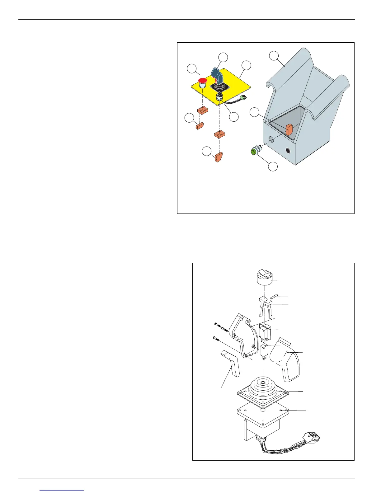
Figure 2-6:
Platform Controls
Refer to
Section 4 - Schematics
for wir-
ing diagrams.
Refer to the
Parts Manual
for replace-
ment part numbers.
A
CCESS
TO
S
WITCHES
1. Remove the four screws from the
control panel and lift the assembly
from the Platform Control box.
2. Unplug the Control Handle wiring
harness.
C
ONTROL
H
ANDLE
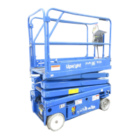
Figure 2-7:
Control Handle
1. Remove the Control Handle, if necessary,
from Platform Control box.
a. Remove the control panel.
b. Unplug the control handle wiring har-
ness.
c. Remove the four screws from the con-
trol handle mounting plate.
d. Lower the control handle through the
control panel.
2. Remove and replace defective parts. Refer
to the
Parts Manual
for repair parts num-
bers.
3
2
4
1
5
7
8
9
6
1. Platform Control Box
2. Platform Control Panel
3. Control Handle
4. Lift/Drive Switch
5. Emergency Stop Switch
6. Horn Button (optional)
7. Contact Block - N.C.
8. Contact Block - N.O./N.C.
9. Contact Block - N.O.
Boot, Steering Rocker
Rocker Pin
Rocker, Steering
Right Handle Half
Steering Switch (2)
Switch, Interlock
Left Handle Half
Boot, Handle
Lever, Interlock
Hall Effect Device