Multifunctional serial to Ethernet module user manual www.tcp232.net
Jinan USR IOT Technology Co., Ltd freda@usr.so
Page 15 /
/
/
/ 9
1 Work
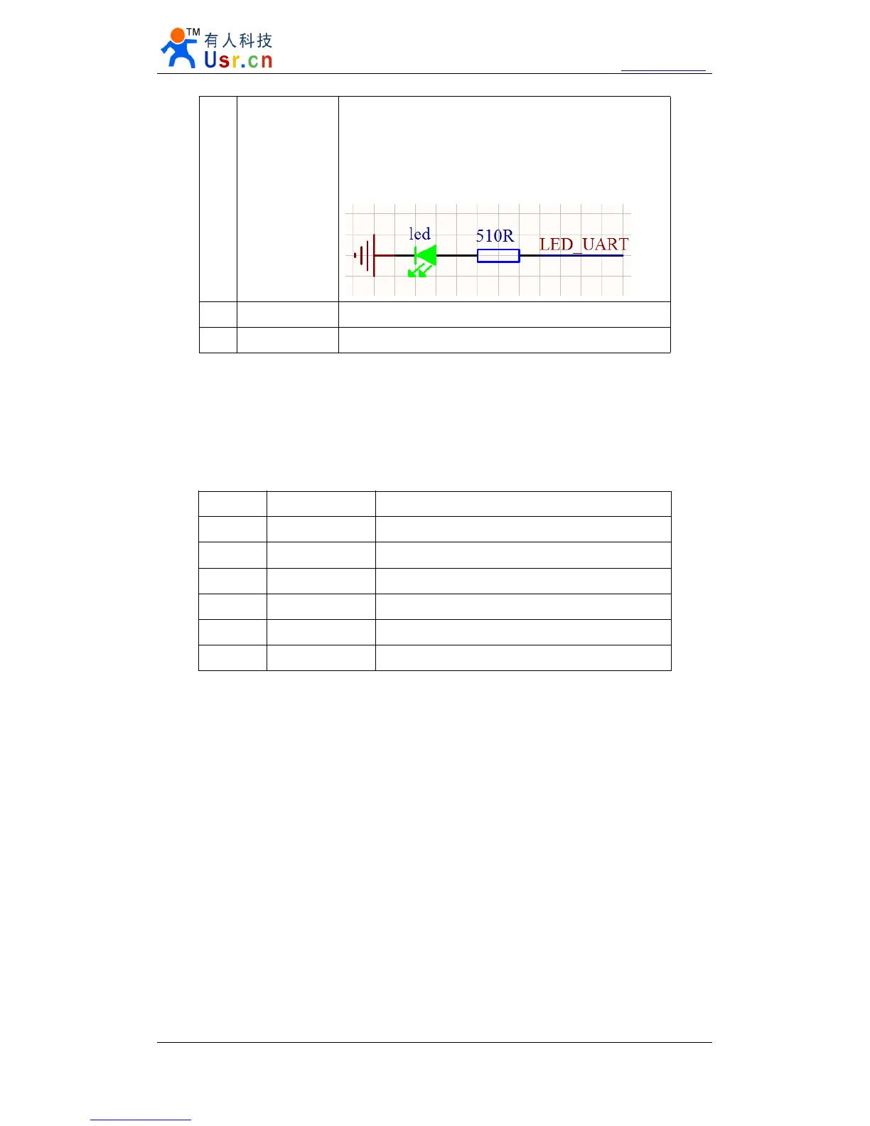
Just interface, have no LED on module,
If you needed, take this pin with LED and 510 ohm
resistor to GND.
See Pin8 for further explantion.
2 Link(green) On RJ45, when ethernet link established, on.
3 Data(yellow) On RJ45, wnen ethernet data communicate, twinkle.
Diagram 3 - 2 LED definition
3.1.4.
3.1.4.
3.1.4.
3.1.4. Serial(TTL)
Serial(TTL)
Serial(TTL)
Serial(TTL) interface
interface
interface
interface
The serial port is TTL level ( 2 * TTL serial port, can be directly connected to MCU ) .
number name Description
1 TXD0 Uart0 transmit data pin
2 RXD0 Uart0 receive data pin
3 CTS0 Uart0 RS232 clear to send
4 RTS0 Uart0 require to send
5 RXD1 Uart1 receive data pin
6 TXD1 Uart1 transmit data pin
Diagram 3 - 3 connector interface(include uart0 and uart1)
Note:
RS485 and RS422 are self adaption ports, according to RS485 connection that is RS485,
according to RS422 connection is RS422 .