Multifunctional serial to Ethernet module user manual www.tcp232.net
Jinan USR IOT Technology Co., Ltd freda@usr.so
Page 9 /
/
/
/ 9
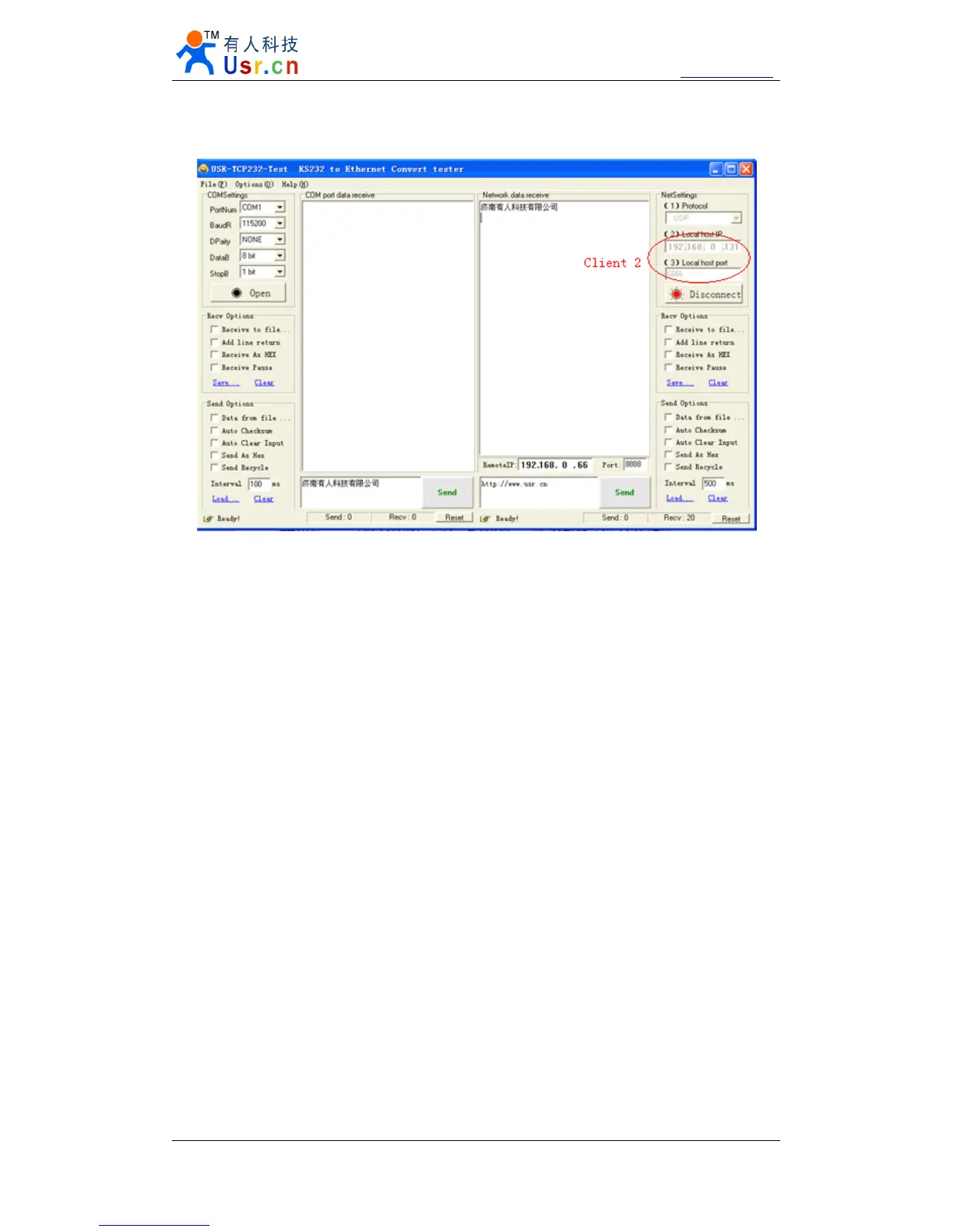
Diagram 7 Client 1 <-> server
Diagram 8 Client 2 <-> server
2.5.
2.5.
2.5.
2.5. TCP
TCP
TCP
TCP Server
Server
Server
Server mode
mode
mode
mode
TCP Server mode have 2 parameters: max link number and link type
1. max link number: 1 ~ 4;
2. Link type: typical, completely transparent, send data to all client;
extend1, communicate with id, otherwise abandon;
extend2, communicate with id, otherwise send to all client.
For link type extended 1 and extended 2:
When receive data from ethernet, module will send data to serial port with head
‘
I
’
‘
N
’
,followed by data.
’
I
’
represent incoming data,
‘
N
’
represent client index.
When user MCU want send data to module serial port, start with head
‘
O
’
‘
N
’
data...
‘
O
’
represent send out,
‘
N
’
represent which client.
When new TCP connection incoming, module will send
‘
C
’
‘
N
’
‘
M
’
to serial port, indicating
that there is current link
‘
N
’
accessed, total link number
‘
M
’
.
When link number have exceed maximum, new link requirment will lead to message
‘
F
’
‘
F
’
.
When disconnect, module will send
‘
D
’
‘
N
’
‘
M
’
, represent current link N is delete, left link
M.
Note:
serial data need to be sent in one package to module.