Multifunctional serial to Ethernet module user manual www.tcp232.net
Jinan USR IOT Technology Co., Ltd freda@usr.so
Page 21 /
/
/
/ 9
4.
4.
4.
4. Paramters
Paramters
Paramters
Paramters configuration
configuration
configuration
configuration
4.1.
4.1.
4.1.
4.1. Web
Web
Web
Web page
page
page
page
Usually, this series of TCP232 module is configured through web pages.
4.2.
4.2.
4.2.
4.2. Serial
Serial
Serial
Serial port
port
port
port
After module already power on, press Reload(for USR-TCP232-E, pull Reload low), module
will go in Serial config mode(in this mode we can config paramters through serial command), then
module serial port 0 will switch to 9600, 8, n, 1, and send char
‘
U
’
, indicating that module already
in serial config mode.
after config complete, module will send
‘
K
’
out, indicating config success;
Verify error will be
‘
E
’
and correct verify byte.
Free Reload(for USR-TCP232-E, pull Reload high), module will save paramters and reboot,
config take effect.
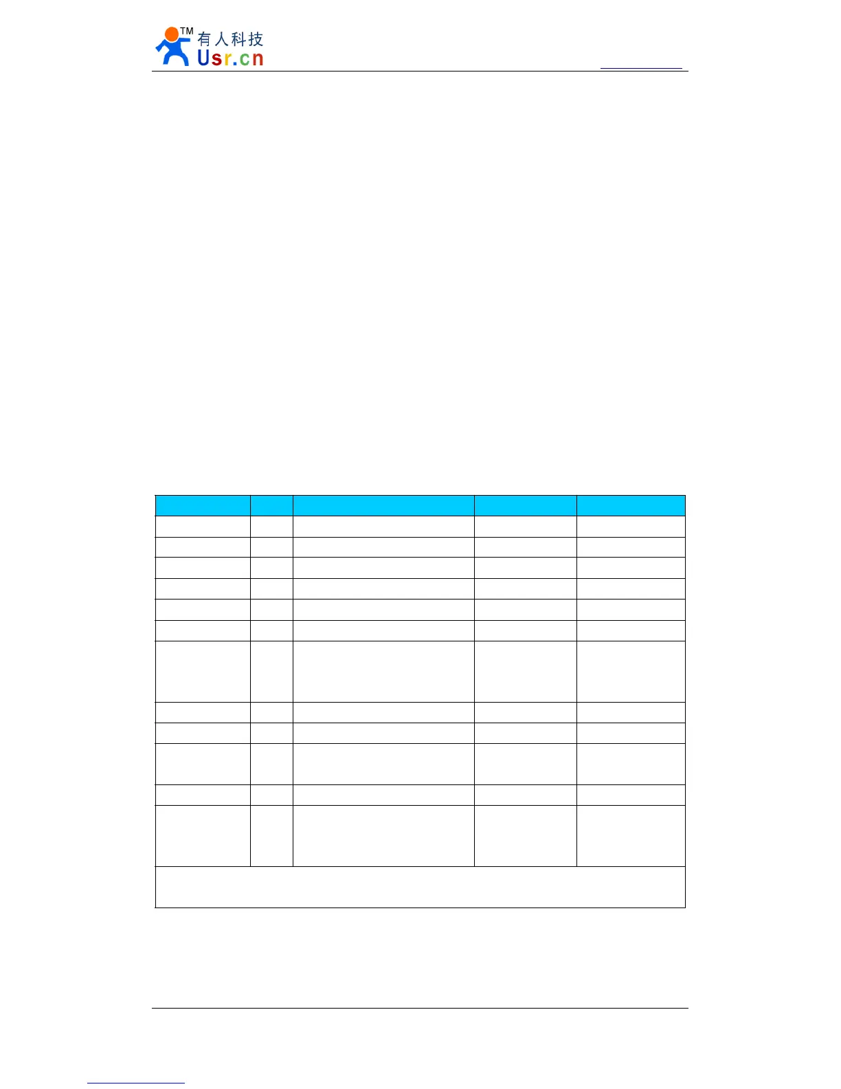
name Byte Description example Hex(low front)
head 2 Head( 55 BA/55 C1/55 C2 ) 55 BA 55 BA
Target IP 4 Target IP 192.168.0.201 C9 00 A8 C0
Target port 2 Target port 8234 2A 20
Module IP 4 Module IP 192.168.0.7 07 00 A8 C0
Module port 2 Module port 20108 8C 4E
gateway 4 Gateway IP 192.168.0.201 C9 00 A8 C0
Work mode 1
1 for TCP Client ; 0 for UDP ; 2
for UDP Server ; 3 for TCP
Server
TCP Client 01
Baud rate 3 Serial baud rate 115200 00 C2 01
serial param 1 Databit s , stopbit s, v erifybit s N,8,1 03
Unique ID 3
ID-H, ID-L, ID-type , 0 for no
use
No use 00 00 00
Subnet mask 4 Subnet mask, low front 255.255.255.0 00 FF FF FF
Sum verify 1
Sum verification, from target
ip until end
(sum itself not included)
sum B9
Total cmd : 55 BA C9 00 A8 C0 2A 20 07 00 A8 C0 8C 4E C9 00 A8 C0 01 00 C2 01 03
00 00 00 00 FF FF FF B9
Diagram 4 - 1 protocol structure and example
Note.
1. Head definition.