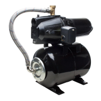
SHALLOW WELL
INSTALLATION
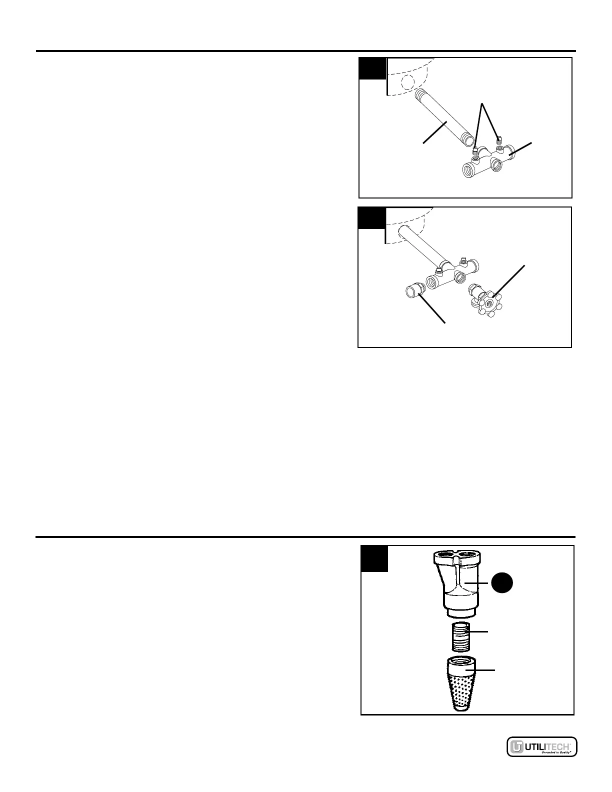
13.
Thread 10 in. x 1 in. nipple into pressure tank (both
not included). Thread tank cross into nipple so that
the two 1/4 in. holes in tank cross face upward. Plug
two outlets on tank cross with two 1/4 in. plugs.
13
14.
Thread 1/2 in. boiler drain into front of tank cross.
Thread 1 in. male PVC adapter into inlet side of tank
cross. Connect to household plumbing.
14
15. IMPOR
TANT: Air pressure in the tank must be 2 PSI
lower than the "cut-in" of the pressure switch. Pump
has a 30/50 PSI pressure switch, so tank pressure
must be set at 28 PSI. Locate the air valve/stem
on the tank and check pressure with a tire gauge (not
included). If air needs to be removed, press down on
valve to bleed off air. Use a tire pump or air
compressor to add air if needed.
NOTE: The tank air pressure must be set when there is
no water in the tank.
DEEP WELL INSTALLATION
1.
Thread 1-1/4 in. close nipple into foot valve. Thread
the other end of 1-1/4 in. close nipple into bottom of
deep well ejector (B). Hand tighten, then tighten 1/4
turn with pipe wrench.
Lowes.com
8
1/4 in. Plugs
T
ank Cross
Nipple
1/2 in. Boiler
Drain
1 in. Male
PVC Adapter
1
1-1/4 in.
Close
Nipple
Foot
V
alve
B