ENGLISH
32
EXTERNAL AERIAL
We suggest to use the external aerial (model: ANSGP433) in
order to guarantee the maximal range.
Connect the antenna hot pole to terminal L1 of the control unit
and the braiding to terminal L2.
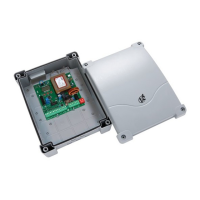
INTERFACE
The ADI (Additional Devices Interface) interface of the control
unit CITY2+ allows the connection to V2 optional modules.
Refer to V2 catalogue or to the technical sheets to see which
optional modules with ADI interface are available for this control
unit.
WARNING: Please read the instructions of each single
module to install the optional modules.
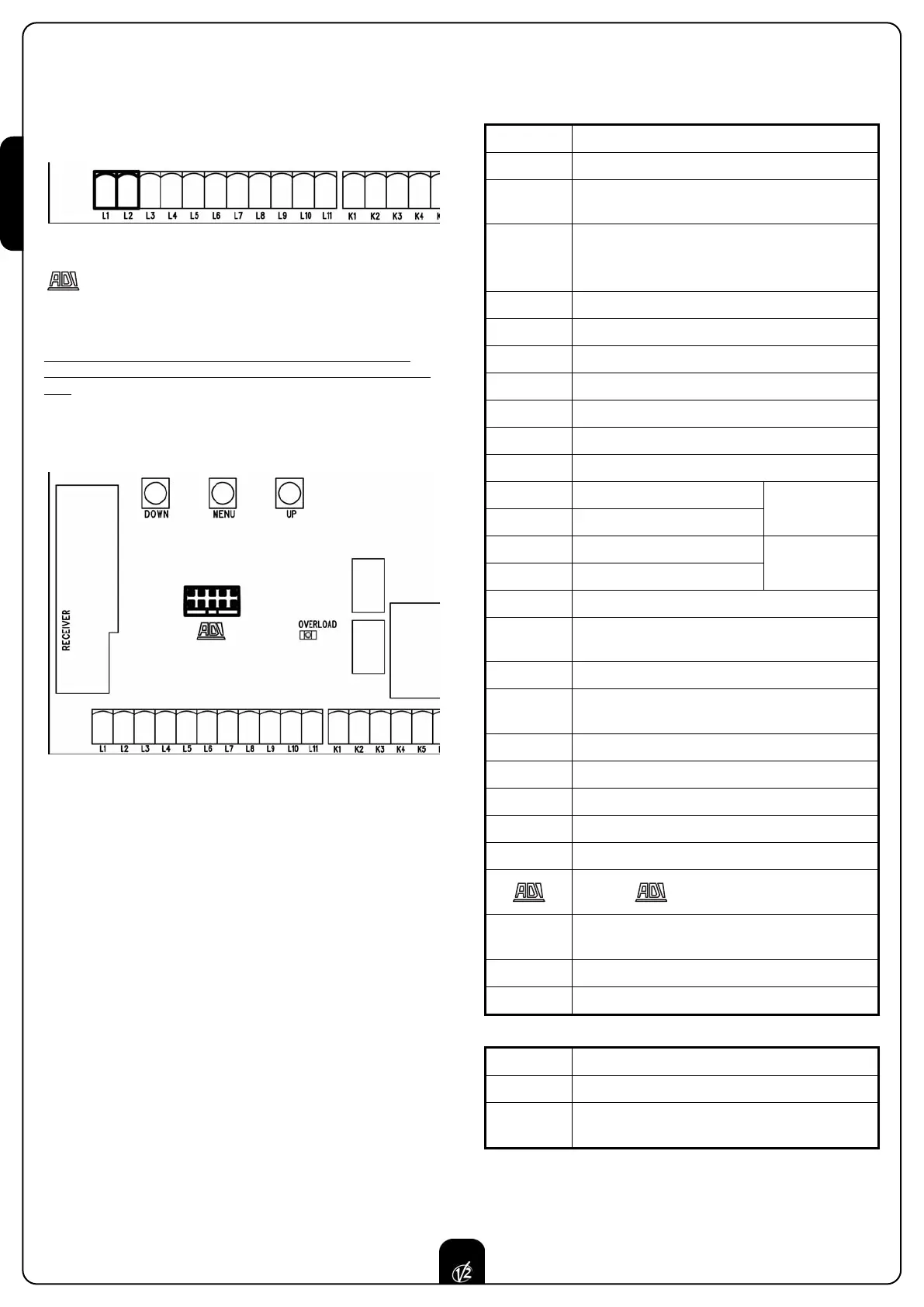
L1 Antenna
L2 Antenna shield
L3
Opening control for the connection of control
devices with N.O. contact
L4
Opening controls for pedestrian access for the
connection of control devices with N.O. contact
L5 Stop command. N.C. contact
L6 Common (-)
L7 Photocells type 1. N.C. contact
L8 Photocells type 2. N.C. contact
L9 Safety ribbons type 1 (fixed). N.C. contact
L10 Safety ribbons type 2 (mobile). N.C. contact
L11 Common (-)
K1 Open limit switch motor 1
K2 Close limit switch motor 1
K3 Open limit switch motor 2
K4 Close limit switch motor 2
K5 Common (-)
K6
Power output +24Vdc for photocells and other
accessories
K7 Common for accessories power supply
K8
Photocell/optical edge TX power supply for
functional test
K9 - K10 LOCK 12V
Z1 - Z2 24 V courtesy light or flashing light
Z3 - Z4 Motor 1
Z5 - Z6 Motor 2
B1 - B2 230VAC courtesy light or flashing light
Interface
OVERLOAD
It shows that there is an overload on accessories
power supply
BAT+ + Pole of optional battery pack (code 161212)
BAT- - Pole of optional battery pack (code 161212)
L Power phase 230 VAC / 120VAC
N Neutral 230 VAC / 120VAC
MAINS It shows that the control unit is power supplied
ELECTRIC CONNECTIONS TABLE
Encoder motor 2
Encoder motor 1