12 • vacon installation
Tel. +358 (0)201 2121 • Fax +358 (0)201 212205
2
2.2.3 Allowed option boards in Vacon20
See below for the allowed option boards in the slot:
Note! When OPT-B1 / OPT-B4 used in Vacon20, +24VDC (±10%, min.300mA) power
should be supplied to Terminal 6 (+24_out) and Terminal 3 (GND) in control board.
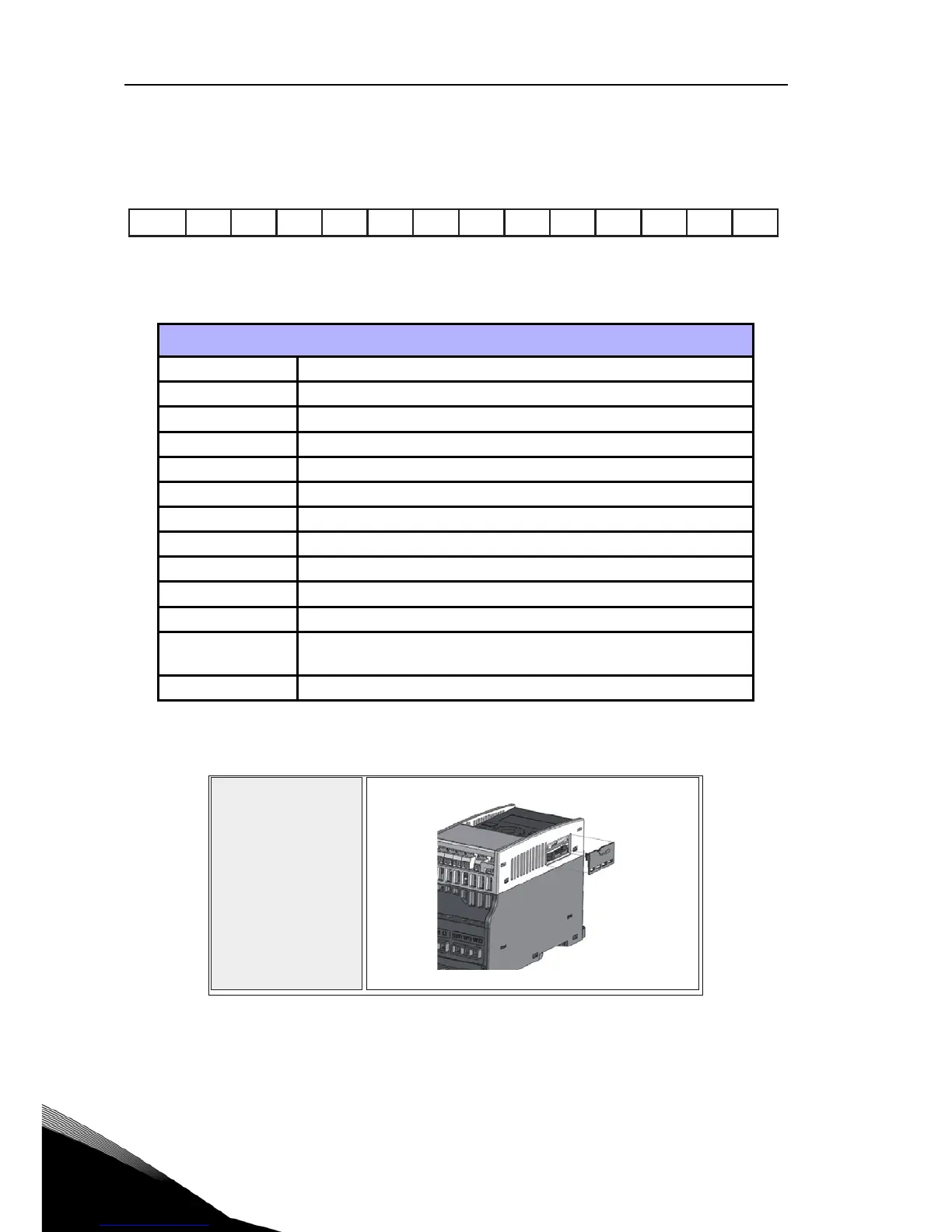
Option board assembly structure:
Option boards (all boards are varnished)
OPT-EC-V EtherCat
OPT-E3-V Profibus DPV1 (Screw connector)
OPT-E5-V Profibus DPV1 (D9 connector)
OPT-E6-V CANopen
OPT-E7-V DeviceNet
OPT-E9-V Modbus TCP, Profinet & Ethernet IP
OPT-B1-V 6 x DI/DO, each I/O can be individually
OPT-B2-V 2 x Relay output + Thermistor
OPT-B4-V 1 x AI, 2 x AO (isolated)
OPT-B5-V 3 x Relay output
OPT-B9-V 1 x RO, 5 x DI (42-240 VAC)
OPT-BH-V
3 x Temperature measurement (support for PT100, PT1000,
NI1000, KTY84-130, KTY84-150, KTY84-131 sensors)
OPT-BF-V 1 x AO, 1 x DO, 1 x RO

 Loading...


