monitoring & parameters vacon • 21
24-hour support +358 (0)201 212 575 • Email: vacon@vacon.com
5
5. MONITORING AND PARAMETERS
NOTE! This guide is for Vacon 20 standard application, if you need parameter de-
scriptions for detail, please download the user manual on: http://drives.dan-
foss.com/knowledge-center/technical-documentation/.
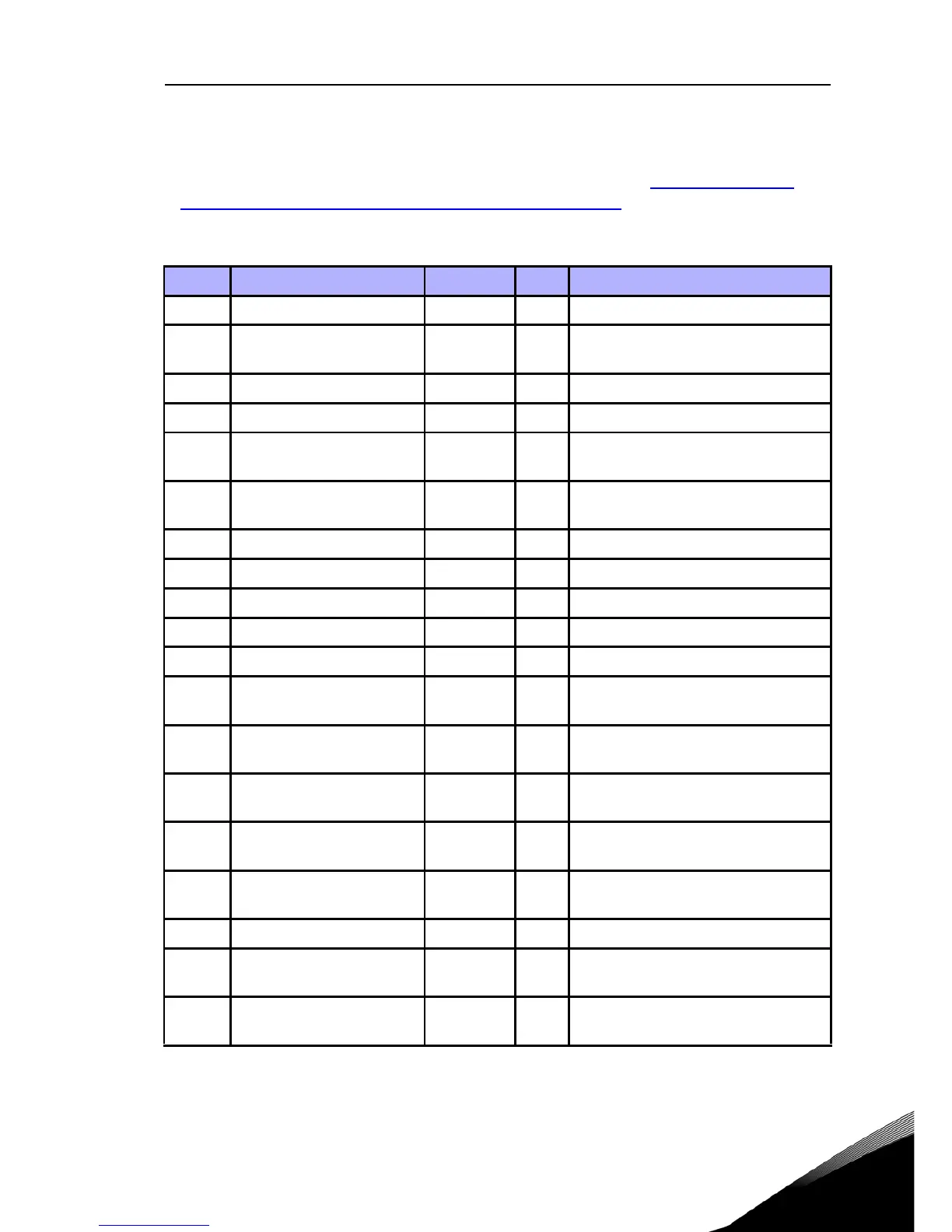
5.1 Monitoring values
Code Monitoring signal Unit ID Description
V1.1 Output frequency Hz 1 Output frequency to motor
V1.2 Frequency reference Hz 25
Frequency reference to motor con-
trol
V1.3 Motor speed rpm 2 Calculated motor speed
V1.4 Motor current A 3 Measured motor current
V1.5 Motor torque % 4
Calculated actual / nominal torque
of the motor
V1.6 Motor shaft power % 5
Calculated actual / nominal power
of the motor
V1.7 Motor voltage V 6 Motor voltage
V1.8 DC-link voltage V 7 Measured DC-link voltage
V1.9 Unit temperature °C 8 Heatsink temperature
V1.10 Motor temperature % 9 Calculated motor temperature
V1.11 Output Power KW 79 Output power from drive to motor
V2.1 Analogue input 1 % 59
AI1 signal range in percent of used
range
V2.2 Analogue input 2 % 60
AI2 signal range in percent of used
range
V2.3 Analogue output % 81
AO signal range in percent of used
range
V2.4
Digital input status DI1,
DI2, DI3
15 Digital input status
V2.5
Digital input status DI4,
DI5, DI6
16 Digital input status
V2.6 RO1, RO2, DO 17 Relay / digital output status
V2.7
Pulse train / encoder
input
% 1234 0 - 100% scale value
V2.8 Encoder rpm rpm 1235
Scaled according to Encoder
pulses / revolution parameter
Table 4: Monitoring values