16 • vacon vacon 20 api
Tel. +358 (0)201 2121 • Fax +358 (0)201 212205
3
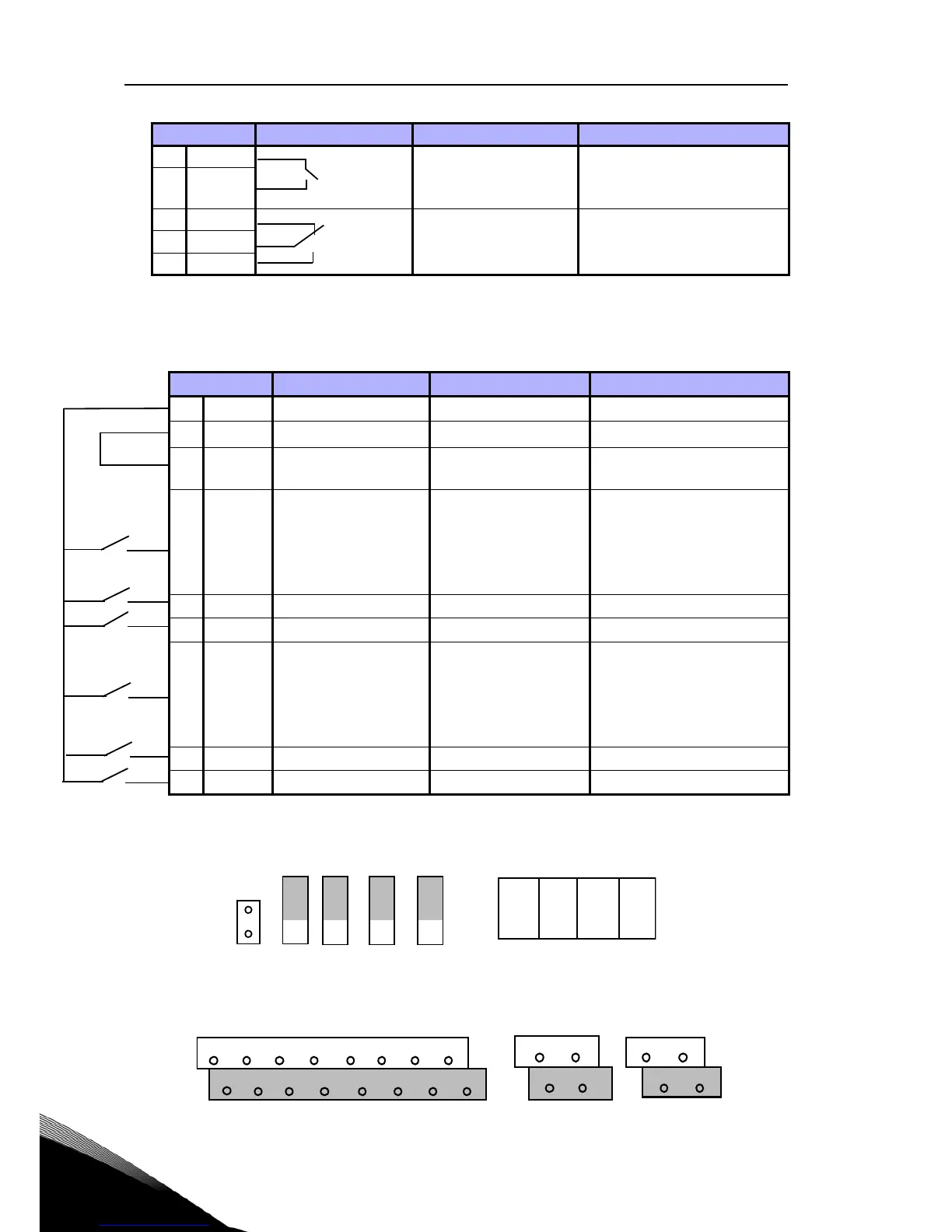
Figure 18: Microswitchs
Vacon 20 I / O terminals:
22 RO1 NO Relay out 1
Active = RUN
P)
Switching load:
250 Vac / 3 A, 24V DC 3A
23 RO1 CM
24 RO2 NC
Relay out 2
Active = FAULT
P)
Switching load:
250 Vac / 3 A, 24V DC 3A
25 RO2 CM
26 RO2 NO
Terminal Signal Factory preset Description
3 GND I / O signal ground
6 24 Vout 24 V output for DI's
%, max load 50 mA
7DI_C
Digital Input Com-
mon
Digital Input Common
for DI1-DI6
8 DI1 Digital input 1
Start forward
P)
Positive, Logic1:18…30V,
Logic0: 0…5V;
Negative, Logic1: 0…10V,
Logic0: 18…30V;
Ri = 10KΩ (floating)
9 DI2 Digital input 2
Start reverse
P)
10 DI3 Digital input 3
Fault reset
P)
14 DI4 Digital input 4
Preset speed B0
P)
Positive, Logic1:18…30V,
Logic0: 0…5V;
Negative, Logic1: 0…10V,
Logic0: 18…30V;
Ri = 10KΩ (floating)
15 DI5 Digital input 5
Preset speed B1
P)
Only for DI.
16 DI6 Digital input 6
External Fault
P)
Only for DI.
Table 2: DI Sink Type, remove jumper J500 and connect the wire using table 2
Terminal Signal Factory preset Description
Table 1: Vacon 20 General purpose application default I / O configuration and
connections for control board
P) = Programmable function, See User Manual: parameter lists and
descriptions for detail

 Loading...


