K1
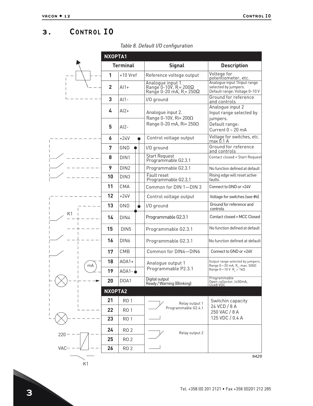
NXOPTA1
NXOPTA2
Terminal Signal Description
1
+10 Vref Reference voltege output
2
AI1+
Analogue input 1.
Range 0-10V, R
i
= 200
Ω
Range 0-20 mA, R
i
= 250
Ω
Analogue input 2.
Range 0-10V, Ri= 200Ω
Range 0-20 mA, Ri= 250Ω
3
AI1-
I/O ground
4
AI2+
5
AI2-
6
+24V
7
GND I/O ground
8
DIN1
Contact closed = Start Request
9
DIN2
10
DIN3
11
CMA
Common for DIN 1—DIN 3
12
+24V
13
GND I/O ground
14
DIN4
Contact closed = MCC Closed
15
DIN5
16
DIN6
No function defined at default
17
CMB
18
AOA1+
Output range selected by jumpers.
Range 0—20 mA. R
L
, max. 500Ω
Range 0—10 V. R
L
> 1kΩ
19
AOA1-
20
21
22
23
DOA1
Digital output
Ready / Warning (Blinking)
mA
9429
Voltege for
potentiometer, etc.
Analogue input 1Input range
selected by jumpers.
Default range: Voltage 0–10 V
Ground for reference
and controls
Ground for reference
and controls
Analogue input 2
Input range selected by
jumpers.
Default range:
Current 0 – 20 mA
Voltage for switches, etc.
max 0.1 A
Start Request
Programmable G2.3.1
Programmable G2.3.1
Fault reset
Programmable G2.3.1
No function defined at default
Rising edge will reset active
faults.
No function defined at default
Connect to GND or +24V
Voltage for switches (see #6)
Ground for reference and
controls
Programmable G2.3.1
Programmable G2.3.1
Connect to GND or +24V
Analogue output 1
Programmable P2.3.1
Programmable
Open collector, I≤50mA,
U≤48 VDC
RO 1
RO 1
RO 1
24
25
26
RO 2
RO 2
RO 2
Relay output 1
Programmable G2.4.1
Relay output 2
Switchin capacity
24 VCD / 8 A
250 VAC / 8 A
125 VDC / 0.4 A
220
VAC
K1
Control voltage output
Programmable G2.3.1
Common for DIN4—DIN6
Control voltage output
 Loading...


