1
vacon • 2 Introduction
Local contacts: http://drives.danfoss.com/danfoss-drives/local-contacts/
1. INTRODUCTION
The DC/DC application creates output according to the needs of the system, and it is possible to
integrate into the system with different topologies. Choosing applicable topology, see the Design
Guide, Hybridization (DPD01887A).
1.1 Application functionality
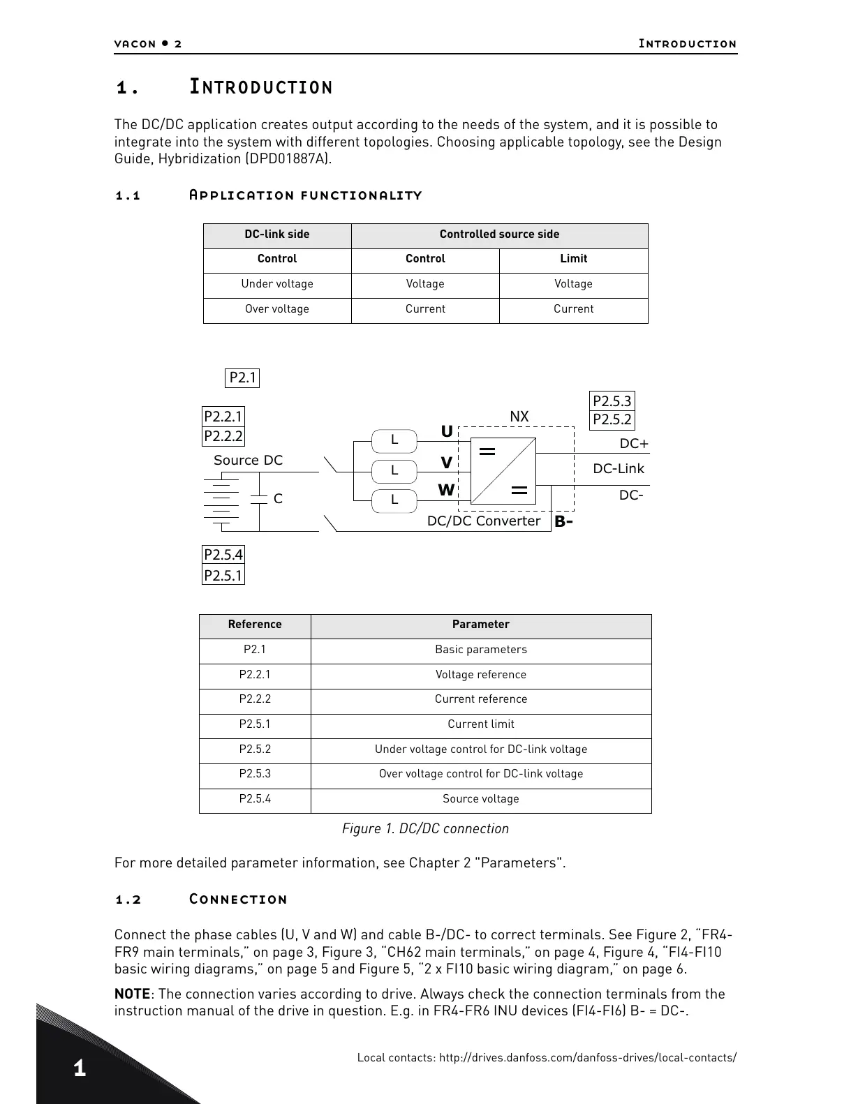
Figure 1. DC/DC connection
For more detailed parameter information, see Chapter 2 "Parameters".
1.2 Connection
Connect the phase cables (U, V and W) and cable B-/DC- to correct terminals. See Figure 2, “FR4-
FR9 main terminals,” on page 3, Figure 3, “CH62 main terminals,” on page 4, Figure 4, “FI4-FI10
basic wiring diagrams,” on page 5 and Figure 5, “2 x FI10 basic wiring diagram,” on page 6.
NOTE: The connection varies according to drive. Always check the connection terminals from the
instruction manual of the drive in question. E.g. in FR4-FR6 INU devices (FI4-FI6) B- = DC-.
DC-link side Controlled source side
Control Control Limit
Under voltage Voltage Voltage
Over voltage Current Current
Reference Parameter
P2.1 Basic parameters
P2.2.1 Voltage reference
P2.2.2 Current reference
P2.5.1 Current limit
P2.5.2 Under voltage control for DC-link voltage
P2.5.3 Over voltage control for DC-link voltage
P2.5.4 Source voltage
P2.5.3
P2.5.2
P2.1
P2.2.1
P2.2.2
P2.5.4
P2.5.1
B-
U
V
W
C
DC-Link
DC+
DC-
DC/DC Converter
L
L
L
Source DC
NX
 Loading...


