STO and SS1 safety functions vacon • 25
Local contacts: https://www.danfoss.com/en/contact-us/contacts-list/
5
5.3.4 External light test pulse filtering capability
To verify the switching capabilities of STO lines' switches, some safety actuators test their outputs
by pulsing the output from low to high level for short periods of time when STO is enabled. The puls-
es are known as 'light test pulses'. Allowed pulse characteristics are introduced in Table 5 in Chap-
ter 5.3.3.
To prevent the test pulses from causing false STO disactivation commands or false fault indications,
the used connection must not create current path through STO inputs. Only connection example 1
is allowed. See the connection examples in chapter 6.1. Only one switch is allowed to be tested at a
time.
5.3.5 Connections
In addition to the STO inputs, the board contains also a thermistor input. If the thermistor input is
not used, it must be disabled. The thermistor input is disabled by making a short circuit to the ter-
minals and setting the jumper X23 in "OFF" state. The thermistor input operation and instructions
are presented in chapter 8.1.
* If 230VAC is used as control voltage from the output relays, the control circuitry must be powered
with a separate isolation transformer to limit short circuit current and overvoltage spikes. This is
to prevent the welding on the relay contacts.
Table 5. Pulse characteristics
Pulse characteristics Dark test pulse Light test pulse
Test pulse length < 4 ms (24 V) < 4 ms (24 V)
Period > 20 ms > 20 ms
Frequency < 50 Hz < 50 Hz
CAUTION! When using other connection than "Connection example 1" with light
test pulse function, forbidden pulse structure or by testing both switches (SW P &
SW M) simultaneously, the drive may enter ready state even if STO should be ac-
tivated. This may cause unintentional rotation of the motor shaft. See the connec-
tion examples in chapter 6.1.
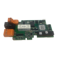
Table 6. OPTBJ I/O terminals
Terminal Technical information
1STO1+
Isolated STO input 1, +24V
2STO1
-Virtual GND 1
3STO2+
Isolated STO input 2, +24V
4STO2-
Virtual GND 2
25 RO1 Relay output 1 (NO) *
Switching capacity:
• 24VDC/8A
• 250VAC/8A
• 125VDC/0.4A
Min. switching load: 5V/10mA
26 RO2
28 TI1+
Thermistor input; R
trip
> 4.0 kΩ (PTC)
29 TI1-