Appendix
24 Installation and maintenance instructions atmoMAG 0020189893_03
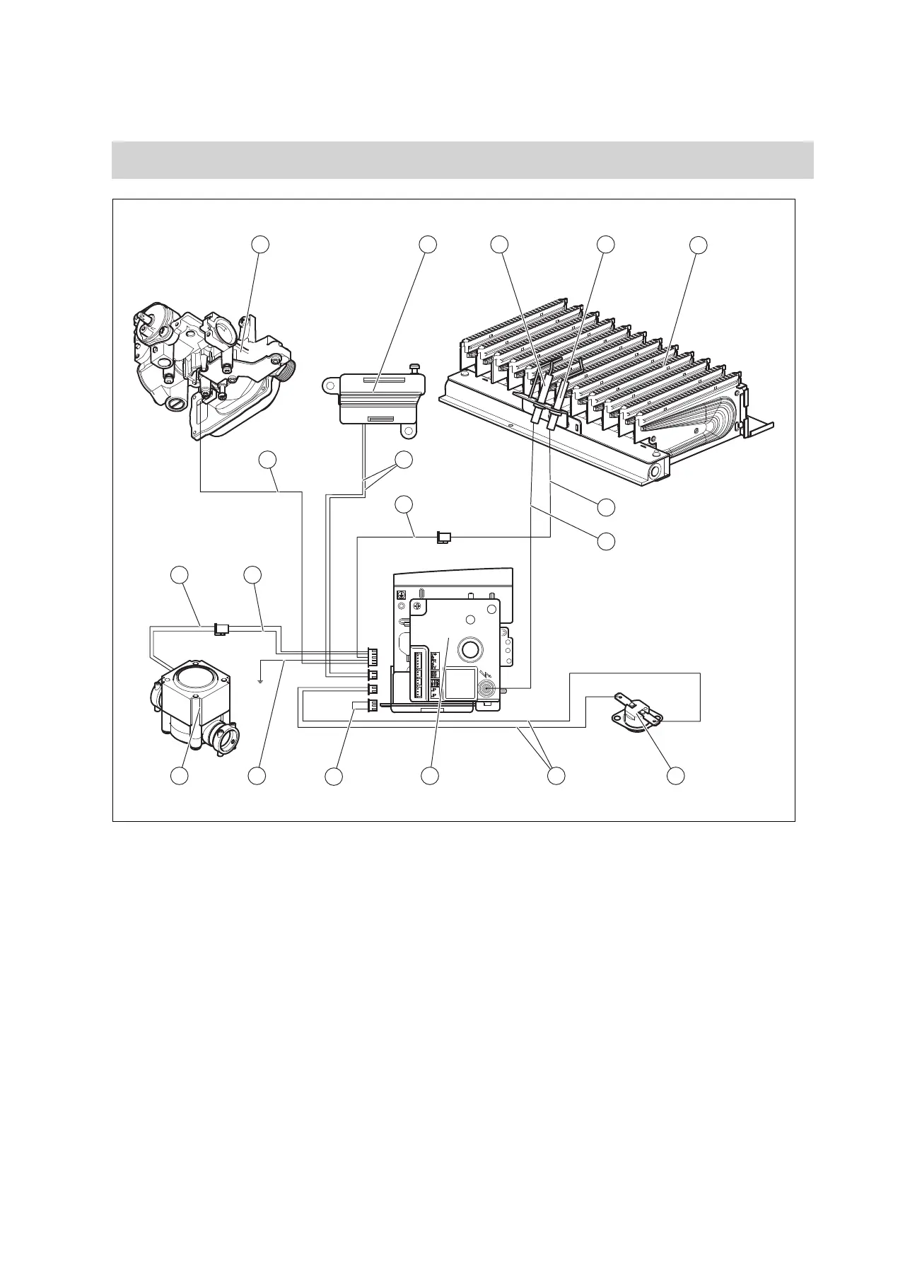
E Type GX connection diagram
Applicability: MAG 11-0/1 GX
OR MAG 14-0/1 GX
1 2 3 4
5
6
7
8101213
14 15
18
16
17
9
11
1 Gas valve
2 Micro switch
3 Ignition electrode
4 Monitoring electrode
5 Burner
6 Red connection cable
7 Transparent connection cable
8 Flue gas sensor
9 Red connection cable
10 Electronics box
11 Yellow connection cable
12 Black connection cable
13 Generator
14 Red connection cable
15 Black connection cable
16 Blue connection cable
17 Orange connection cable
18 Green connection cable

 Loading...