Chapter 14 _________________________________________________________ Output Interfaces
VAISALA _______________________________________________________________________ 73
CHAPTER 14
OUTPUT INTERFACES
This chapter describes the serial communication settings and outputs
of the DM500.
C NO NC
REL 1
C NO NC
REL 2
1
2
3
4
5
6
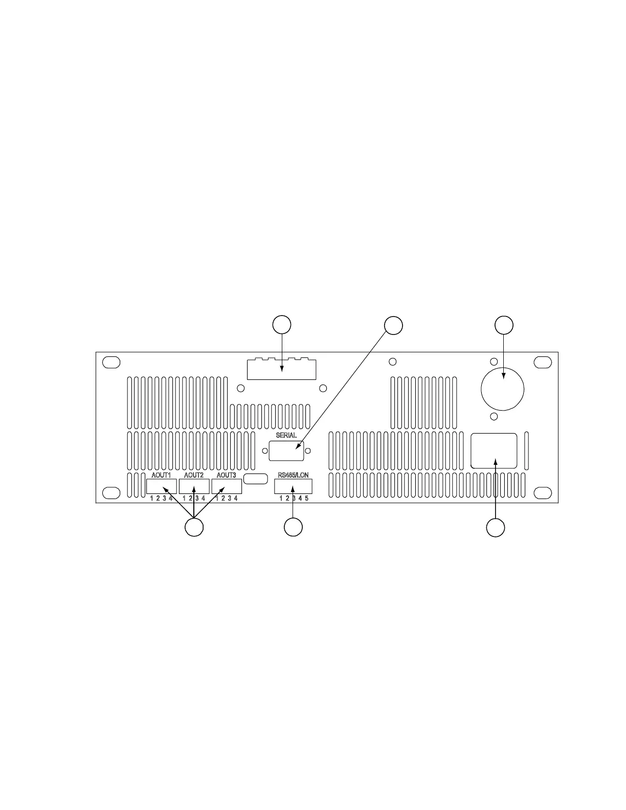
Figure 21 DMI500 User Interface Unit Back Panel (Same as
Figure 3)
The following numbers refer to Figure 21 above:
1 = Relay outputs (optional)
2 = Serial port (EIA-232, RS232 for Terminal/MI70-link
3 = Connection to DMP501
4 = Mains cable
5 = RS485 and LonWorks-port (optional)
6 = Analog outputs (optional)



 To Next Page