Chapter 2 ________________________________________________________Product Overview
VAISALA
_______________________________________________________________________ 13
Loran-C system contains the following additional units:
- VLF-Navaid Processor MWV2xx
- DC Power Supply ±15V MWP302 (replaces MWP411)
- External Power Unit 212822MW
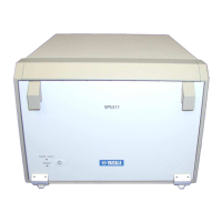
Front Panel
General
The power control switch and the system indicator LEDs are located
on the Front Panel. The power control dip switches are located on the
backside of the Front Panel.
Power Control Switch
The power of the subsystem can be switched on and off from the
Power Control Switch located on lower left corner of the Front Panel.
It is marked with the symbol
Indicator LEDs
The Standby and Power/Status indicator LEDs are located on lower
left corner of the Front Panel beside the Power Control Switch.
The status of the subsystem is indicated by the two LEDs as shown in
Table 3.
Table 3 Indicator L
ED colors
Standby
LED Color
Power/Status
LED color
System Status
blank blank power is not applied
yellow blank power is applied
blank blinking green powering up
blank green ready for operation
blank red unit failure during power up or during
operation, failure in network connection
 Loading...