52
Model Code Page
21. Engine
6000--8750
212 2
1. 9. 1992
1. 1. 1994
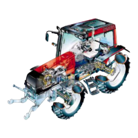
5. Measure the clearance between the valve stem and the
valve guide wit h a dial gauge. Lift the valve so that the valve
head is 15 mm from the face of the cylinder head, and
measure the clearance. It must not be greater than 0,30 mm
for the inlet valves and 0,35 mm for the exhaust valves. In
ordertoestablishthevalveguidewear,anewvalveshouldbe
used when measuring.
D. Changing valve guide s
9101 65800
1. Press or knock out the old guides using drift 9101 65800.
Clean the valve guide locations.
2. Lubricate the outside of the new guides and fit them using
drift 9101 65900, which ensures the correct fitting height (21
mm over the spring face)
21 mm
9101 65900
3.Theguidesarethesamefortheinletandexhaustvalves.
Ensure that the steepest chamfer on the guide, faces the valve
head. Check that the valves do not bind in the guides.
E. Machining valve seat
Machine the damaged valve seat with millingcutter (seepage
210/10). If the width of the seat exceeds 2,3 mm in exhaust
and 3,7 mm in intake, it should be reduced primarily at the
outer edge.
The valve seat angle is 45˚+20’ for exhaust valve and
35˚+20’ for inlet valve.
https://www.truck-manuals.net/
 Loading...