56
Model Code Page
21. Engine
15. 5. 1996
6000--8750
212 6
1. 1. 1995
6. Crank the engine until the aligning marks on the idler gear
and camshaft gear are facing each other. Extract the cam-
shaft.
7. Separate the camshaft from the gear wheel using a press
or suitable drift.
8. Clean the parts which are to be refitted.
9. Fit the key in its groove. Heat t he camshaft gear to 200˚C
in an oven and fit it on the shaft.
10. Lubricate bearing surfaces and lobes and insert the shaft
in the cylinder block. Ensure that the aligning marks on the
gears agree.
11. Fit the timing gear casing cover and the crankshaftV---belt
pulley and hub.
12. Free the pushrods and fit the rocker arm mechanism.
Adjust the valves. Fit the valve cover and the breather pipe
and the inlet pipe between the turbocharger and the induction
manifold.
13. Fit the alternator. Fit the fan and the fan belt.Fit theradiator.
C. Adjusting valves
Note! Valmet 6400 DW, 6800 DWI and 8450 DW tractors have
a by---pass turbo. The adjusting rod of this turbo should be
released before removing the valve cover. Detach the front
end joint of the rod. Do not detach the rod rear end from the
membrane box since then the by---pass passage opening
pressure changes. Before adjustment, also remove the
silencer,fan space protective frame (if fitted), radiator support
iron in the upper part and the boost pipe (if fitted), after which
the valve covers can be removed.
0,35
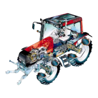
The valve c learance, which can be adjusted on a hot or cold
engine, is 0,35 mm for both inlet and exhaust valves. The
clearanc e is adjusted when the respecti ve piston is at T.D.C.
in the compress i on stroke. The valves for the different cylin-
ders are adjusted in the same sequence as the order of injec-
tion.
--- slacken the lock nut of the adjusting screw
--- measure clearance with a feeler gauge. The clearance is
correct when a 0,35 mm feeler gauge is slightly tight---fitted
between the rocker arm and the valve stem end. Adjust clear-
ance by rotating the adjusting screw.
--- tighten the locking nut and check the clearance
320---engines
Check the valve clearances in the injection order of the en-
gine. Injection or der is 1---2---3.
--- check valves in the 1st cylinder, when the exhaust valve of
no. 3 cylinder is completely open (valve no. 6)
--- check valves in the 2nd cylinder, when the exhaust valve of
no. 1 cylinder is completely open (valve no. 2).
--- check valves in the 3rd cylinder, when the exhaust valve of
no. 2 cylinder is completely open (valve no. 4).
420---engines
--- rotate the crankshaft in the running direction until the valves
in the 4th cylinder are rocking (exhaust closes, inlet opens).
Check the valve clearance of the 1st cylinder
--- Rotate the crankshaft by 1/2 of a turn in the running direc-
tion so that valves in the 3rd cylinder are rocking. Check
valves in the 2nd cylinder
--- continue according to the order of injection:
Injection order
1243
V alves rock in cyl. no 4312
620---engines
--- rotatethe crankshaft in the running direction until thevalves
in the 6th cylinder are rocking (exhaust closes, inlet opens).
Check the valve clearance of the 1st cylinder
--- rotate the crankshaft by 1/3 of a turn in the running directi-
on so that valves in the 2nd cylinder are rocking. Check valves
in the 5th cylinder
---continue according to the order of injection:
Injection order
153624
V alves rock in cyl. no 624153
I
P
I
P
I
P
I
PI
P
I
P
I
P
320, 620, 634
420
I=inlet P=exhaust
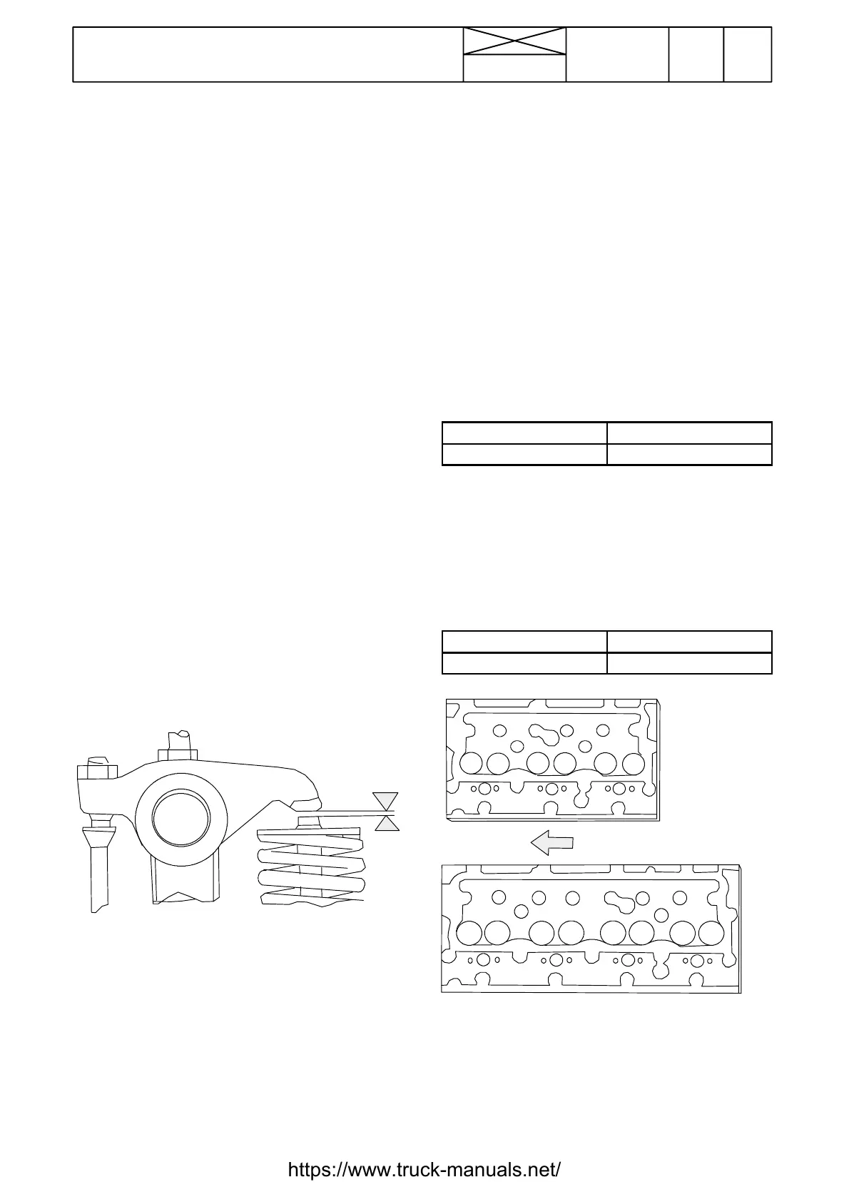
Note! With effect from engine serial no. C6828, the support
strips have been added onto the valve covers. These strips
prevent the gasket from moving inwards. At the same time the
cover manufacturing accurancy has been improved. Spare
part numbers of the covers do not change.
https://www.truck-manuals.net/
 Loading...