VAMP 130 Overcurrent and earth-fault relay
Technical Description
VAMP Ltd
8
Vamp 24h support phone : +358 (0)40 573 6316 VM130.EN003
SCntr Start counter (Start) reading
TCntr Trip counter (Trip) reading
1-N, 2-N
3-N
Fault type/single-phase fault
e.g.: 1-N = fault on phase L1
1-2, 2-3
1-3
Fault type/two-phase fault
e.g.: 2-3 = fault between L2
and L3
Type
1-2-3 Fault type/three-phase fault
Flt pu Max. value of fault current as
compared to In
Load pu 1 s mean value of pre-fault
phase currents IL1…IL3
Recorded
values
EDly % Elapsed time as compared to
the set operate time, 100% =
tripping
The low-set stage (I>) of the overcurrent unit can be configured
for inverse time characteristic. Four sets of characteristic curves
according to IEC 60255-3 are available for the low-set stage, i.e.:
Normal Inverse (NI), Very Inverse (VI), Extremely Inverse (EI)
ja Long Time Inverse (LTI). The mathematical expressions and
the curve sets are given in Figs. 2.2.1.-3, -4, -5 and -6.
Limitations:
1. The maximum measured current is 50 x I
n
. This limits the
scope of inverse curves when the setting is more than 2.5 x
I
n
. E.g. at setting 4 x I
n
the maximum setting relative current
is 12.5 x I
set
/I
n
although the curves are defined up to 20 x
I
set
/I
n
2. The fastes possible operating time is about 60 ms at inverse
time characteristic according to curve types VI and EI.
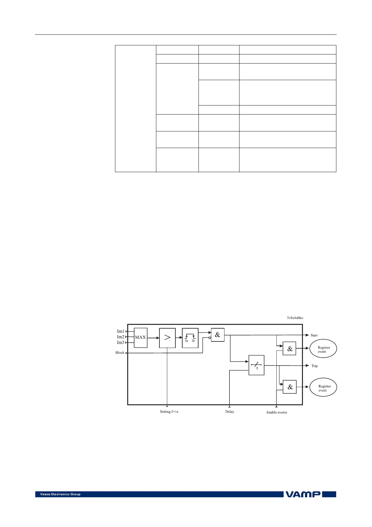
Figure 2.2.1-2 Block diagram of the three-phase overcurrent stage I>>.