VAMP 130 Overcurrent and earth-fault relay
Technical Description
VAMP Ltd
20
Vamp 24h support phone : +358 (0)40 573 6316 VM130.EN003
2.3. Measurement functions of the relay
Measured values
Phase currents I
L1
, I
L2,
I
L3
Measuring range 0 – 50 x In In = 1A or 5A
Residual current I
0
Measuring range 0 – 5 I
0n
I
0n
= 1A or 5A
Frequency f
Measuring range 16 - 65 Hz
Calculated values
From the measured values the relay calculates the following:
x IL
x I2/I1, I2/In
x IL1rms, IL2rms, IL3rms, Ilrms
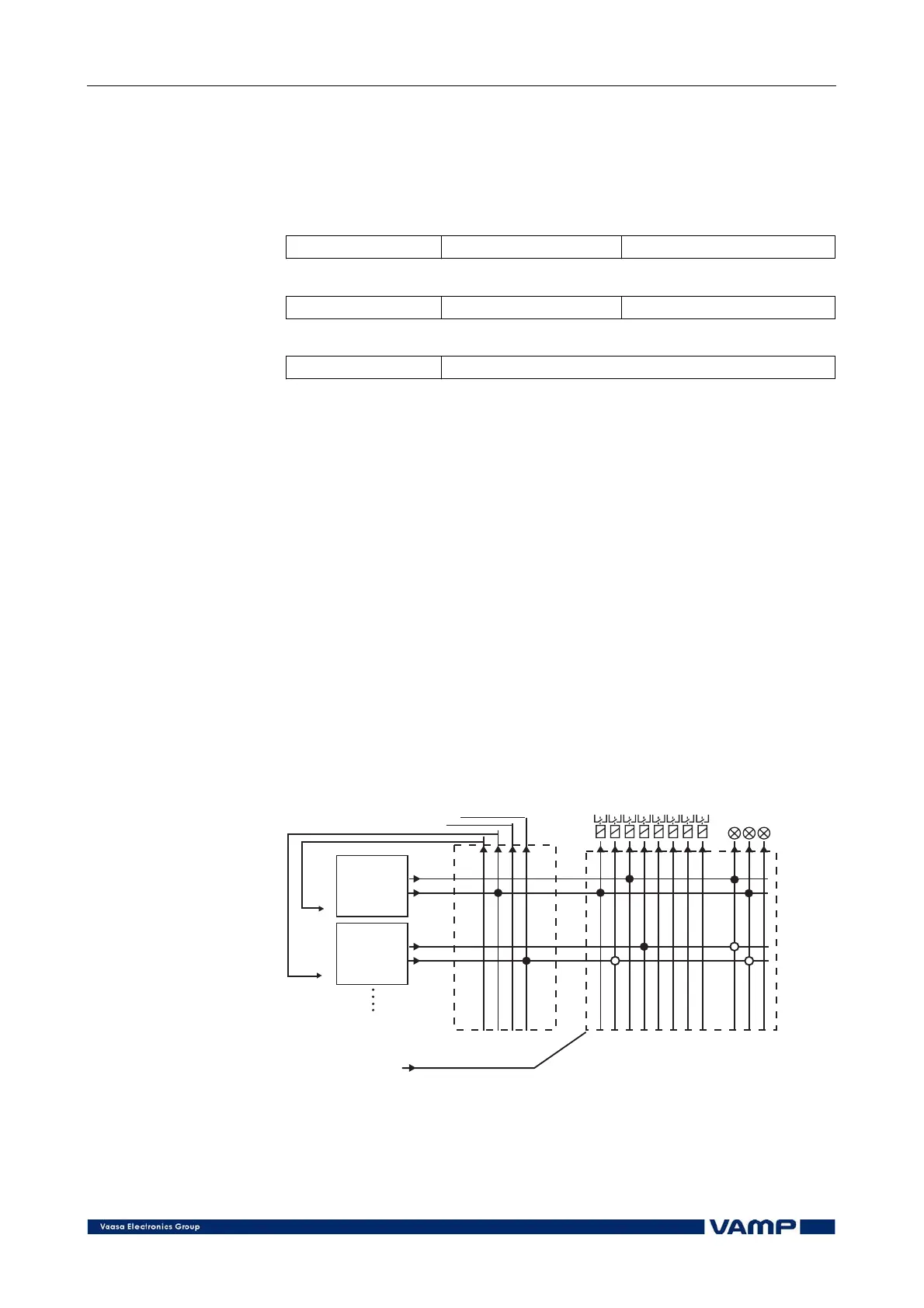
2.4. Output relay and blocking functions
In the VAMP 130 relay all start and trip signals of the
protection stages can be freely routed to the output relays and
operation indicators according to the requirements of the
application. The functions can also be blocked and for this
purpose both internal relay signals and external control signals
can be used. Figure 2.4-1 shows the operating principle of the
grouping and blocking matrix.
Block
Block
Stage 1
Stage 2
Start
Trip
Start
Trip
Operation
indicators
Output relays
relematriisi
Relay matrixBlock matrix
Reset all latches
Figure 2.4-1 Operating principle of the grouping and blocking matrices.