VAMP 130 Overcurrent and earth-fault relay
Technical Description
VAMP Ltd
32
Vamp 24h support phone : +358 (0)40 573 6316 VM130.EN003
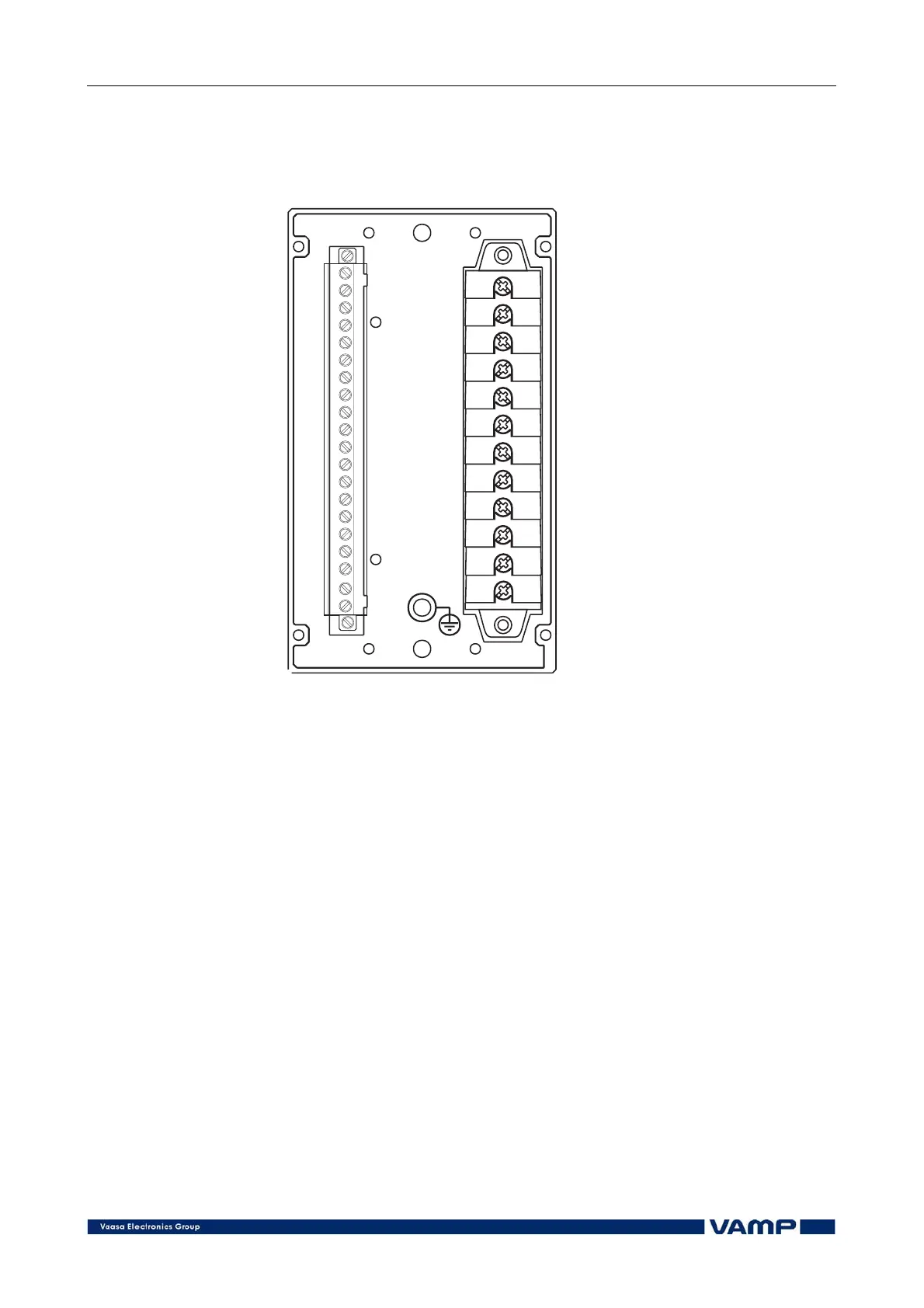
4. Connections
8
20
17
18
19
14
15
16
11
12
13
10
9
12
11
10
9
7
8
6
7
6
4
5
3
1
2
X2
5
4
3
2
1
X1
vamp130takapan
Figure 2.4.2-1 Connections on the rear panel of the VAMP 130 relay.
The VAMP 130 relay is connected to the protected object
through the following measuring and control connections:
x Phase currents IL1, IL2 and IL3 (terminals X1: 1-6)
x Residual current I0 (5 A input: terminals X1: 9-10, 1 A input:
terminals X1: 7-8)
4.1. Digital input
Further the relay can collect position information and alarm
signals via the digital input (terminals X2: 4-5) and store the
information in the event register.
The digital input can be used to:
x Block protection stages under certain conditions.
x Get time stamped event code from any auxiliary
contact.
x Control the output relays.
x Supervise the trip circuit.