4 Wiring and Mounting Diagrams
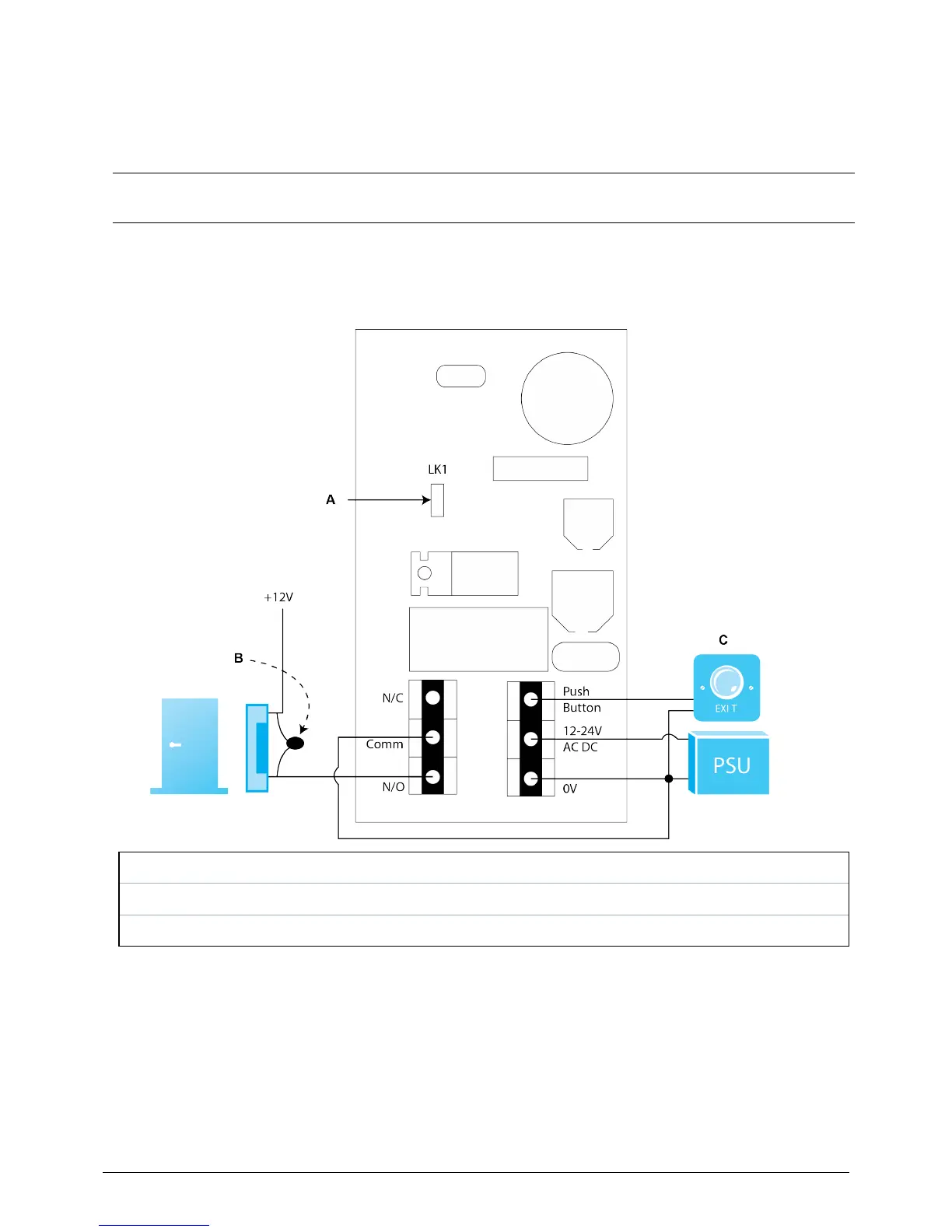
4.1 ACT 5e wiring diagram
Notes:
l Thisillustrationshowswiringfornormallyde-energisedlocks.Ifnormallyenergisedlocksare
requiredusetheN/Crelaycontacts.
l TheACT5emaybepoweredfrom12or24VACorDV.
A Powerupwithoutlinkifprogrammingcodehasbeenlost.
B IMPORTANT:Alwaysplacevaristoracrosslockterminals.
C DoorReleasebutton
© Vanderbilt 2018 8
A-100443
31.01.2018