CONNECTION 0-10 V SIGNAL 21
CONNECTION 0-10 V SIGNAL (BUILDING MANAGEMENT SYSTEM
APPLICATION)
With 1-10V the flow can be set steplessly between the minimum and maxi-
mum flow of the ventilation unit.
This corresponds to the following values:
DX4 DX5 DX6
1 V 40 m³/h 50 m³/h 60 m³/h
1 – 10 V Linear correlation Linear correlation Linear correlation
10 V 400 m³/h* 500 m³/h* 600 m³/h*
Before starting any work, make sure that the ventilation unit is de-energized.
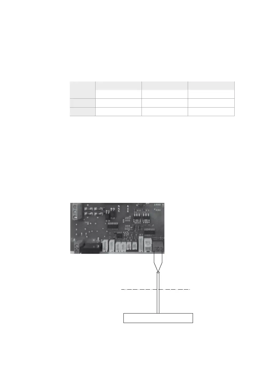
To connect a 0-10 V signal, the cover on the ventilation unit must be
opened in the correct way in order to reach the circuit board. To do this,
remove the screw and tilt the cover plate away from the ventilation unit.
Then a correct cable must be guided to the circuit board via the grommet
provided for this in the ventilation unit. Finnaly, connect the control signal
to terminal X26 “Building management system connection”, according to
the following diagram.
X9
DX4 / DX5 / DX6 circuit board
X8
X5 X21 X20 X15 X26
X6 X22 X23
Provided grommet in
ventilation unit.
2 x 1,5 mm
2
(max)
Building management system
0-10 V signal Ground
*the indicated air flows are in function of and dependent on the total pressure loss of the ventilation
system to be overcome.