3 Design and Function
3.1 Design
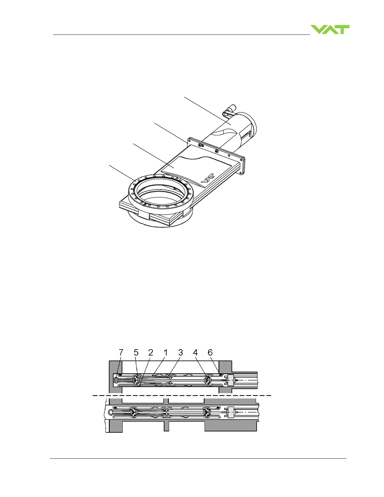
1 Sealing surface
2 Valve body
3 Bonnet flange
4 Actuator
Figure 3-1
3.2 Function
The valve features the VATLOCK sealing technology. This means, the valve is mechani-
cally locked in the closed position. In the open position, the mechanism is not locked. Leaf
springs hold gate and counter-plate against the carriage with the ball retainers. The ball
pairs are in the detents. For closing, the mechanism is moved forward into the closing
position. The locking starts after the leaf spring stop touches the body. The ball retainers
move the ball pairs out of the detents. Gate and counter-plate are spread apart. The gate
seal is pressed against the sealing surface without scuffing. The arrangement of the ball
pairs ensures an increase of the sealing force with vacuum on either side of the gate.
During opening the movements proceed in the reverse order. See «Figure 3-2».
1 Valve gate
2 Counter-plate
3 Leaf springs
4 Ball pairs
5 Ball detents
6 Gate seal
7 Spring stop
Figure 3-2
 Loading...


