Installation, Operating & Maintenance Instructions
Series 64, DN 63-400 (I.D. 2
1
/2" - 16")
VAT Vakuumventile AG, CH-9469 Haag, Switzerland
Tel +41 81 771 61 61 Fax +41 81 771 48 30 CH@vatvalve.com www.vatvalve.com
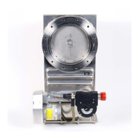
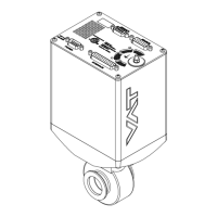
2.2.4 Actuator position (example)
Note: For actuator position of your valve refer to the dimension diagram of your valve.
2.2.5 Compressed air connection by external solenoid (option)
Required solenoids: - Two 5/2 way valves
Air connections : - Adapter with internal thread R
1
/8“ (
1
/8“ NPT for USA) mounted to the pipe thread screws 'A' and 'B'
instead of the solenoids. The pipe thread screws have also the function of an orifice for air pressure
reduction. They must not be removed or replaced.
- L-type connection 'C' with internal thread R
1
/8“ and integrated orifice for air pressure reduction (DN
63 - 200: 1.4 mm, DN 250 - 400: 1.8mm)
Apply compressed air pressure according the following table:
Actuator on „A-position“ (Standard)
Actuator on „B-position“ (Option)
1 = air pressure 0 = no air pressure

 Loading...