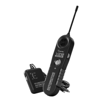
Automotive Short And Open Finder
8
For step by step directions please refer to point 2.8– Locating Sho Circuits, for some hints
and specic dierences refer to the notes below:
The type and size of load connected to the circuit ( impedance or resistance to ground )
determines the amount of current allowed to ow in the circuit. Small loads (low wattage
lamps, electronic systems, etc.) will reduce the range of the V210 receiver accordingly.
In cases where the full range of the V210 receiver is required to follow the wire, it may
prove advantageous to use one of the two methods described below:
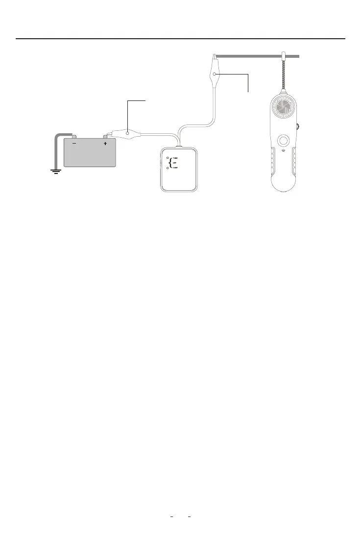
• Tracing wires downstream (from supply to load): replacing the load for a full sho
circuit allows the V210 receiver to work at its maximum capabilities. Before proceeding,
remove all electrical power from the circuit, connect the V210 transmitter in series with
the wire to trace, sho circuit the load to ground (refer to Fig.5 and Fig. 6 ), then
reconnect power and follow instructions in section 2.8 –Locating Sho Circuits.
When you have nished tracing the wire, disconnect the test leads, set the V2107.
transmitter to “OFF” position and loose the “TEST” button.
Figure 4
V210 Receiver
Black Negative
Wire
Red Positive
Wire
V210 Transmitter