14
15
Operation
Operation
CAUTION
Loose welding terminal connections can cause overheating and r esult in the male plug
being fused in the terminal.
22. Power switch
before using the machine. Pull the switch to the closure state of “AN” to operate the
machine, and pull the switch to “AUS” after use. Turn off the power input, and the machine
will stop operating.
21. Gas input port
The gas port is connected with the gas valve output port. After connection, check whether
there is gas leakage.
20. Program downloading port
Change the program downloading connection port, and use the plastic cover to prevent
the dust from polluting and oxidizing the port after use.
19. 5 Pin Control Socket
The 5 pin receptacle is used to connect a trigger switch or remote control to the welding
Power Source circuitry:
To make connections, align keyway, insert plug, and rotate threaded collar fully clockwise.
1
2
3
4
5
9
11
6
7
8
13
12
10
3.2 Control Panel
.Gas Pre-Flow 1
Absolute setting range 0.1s to 5s (0.1S increments)
This parameter operates in TIG modes only and is used to provide gas to the weld zone
prior to striking the arc, once the torch trigger switch has been pressed. This control is
used to dramatically reduce weld porosity at the start of a weld.
2.Initial Current
The main current Setting range 10AMP to 200AMP
This parameter operates in (4T) TIG modes only and is used to set the start current for TIG.
The Start Current remains on until the torch trigger switch is released after it has been
depressed.
Note: The maximum initial current available will be limited to the set value of the base
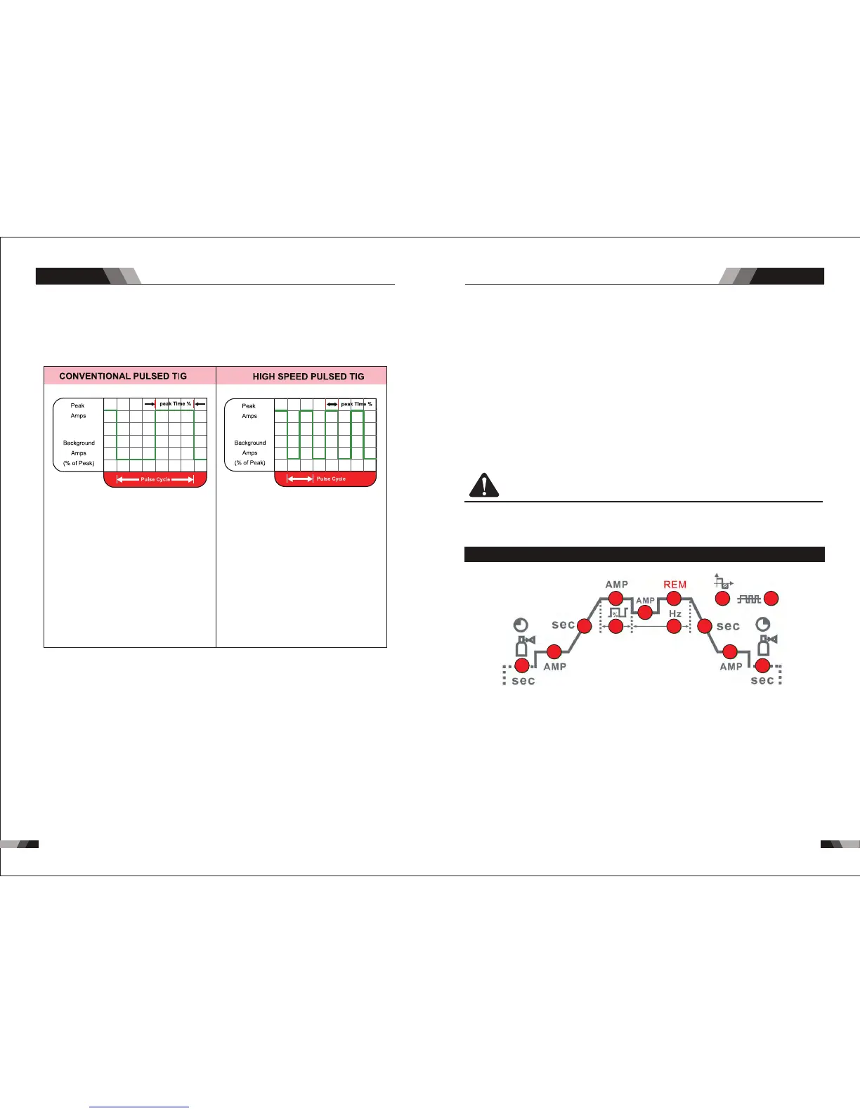
14. Pulse Button
Press the PULSE button to toggle Pulse On and OFF.
Typically from 1 to 10 PPS. Provides a heating
and cooling effect on the weld puddle and can
reduce distortion by lowering the average
amperage. This heating and cooling effect also
produces a distinct ripple pattern in the weld
bead. The relationship between pulse frequency
and travel speed determines the distance
between the ripples. Slow pulsing can also be
coordinated with filler metal addition and
increase overall control of the weld puddle
In excess of 40 PPS, Pulsed TIG becomes more
audible than visible-causing increased puddle
agitation for a better as-welded microstructure.
Pulsing the weld current at high speeds-between
a high Peak and a low Background amperage-
can also constrict and focus the arc.This results
in maximum arc stability, increased penetration
and increased travel speeds(Common Range:
100-500 PPS).
The Arc-Sharpening effects of high speed
pulsing are expanded to new dimensions. The
ability to pulse at 5,000PPS further enhances
arc stability and concentration potential-which
is extre mely beneficial to automation where
maximum travel tspeeds are required.
15. Programming Parameter Indicators
These indicator lights will illuminate when programming.
16. Positive Welding Terminal
Positive Welding Terminal. Welding current flows from the Power Source via heavy
du ty bayonet type terminals. It is essential, however, that the male plug is inserte d
and turned securely to achieve a sound electrical connection.
and turned securely to achieve a sound electrical connection.
17. Negative Welding Terminal
Negative Welding Terminal. Welding current flows from the Power Source via heavy
du ty bayonet type te rmi nal s. It is essential, however, that t he male plug is inserted
18. Shielding Gas Outlet
The Shielding Gas Outlet located on the front panel is a fast connection of a suitable
TIG Torch.
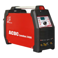
AC/DC WIG SERIES EQUIPMENTAC/DC WIG SERIES EQUIPMENT
13. Process Selection Button
The process selection control is used to select the desired welding mode. Two modes
are available, GTAW (TIG), and MMA (Stick) modes.