0908
Summary
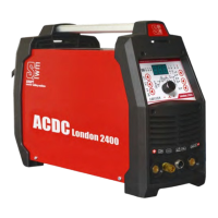
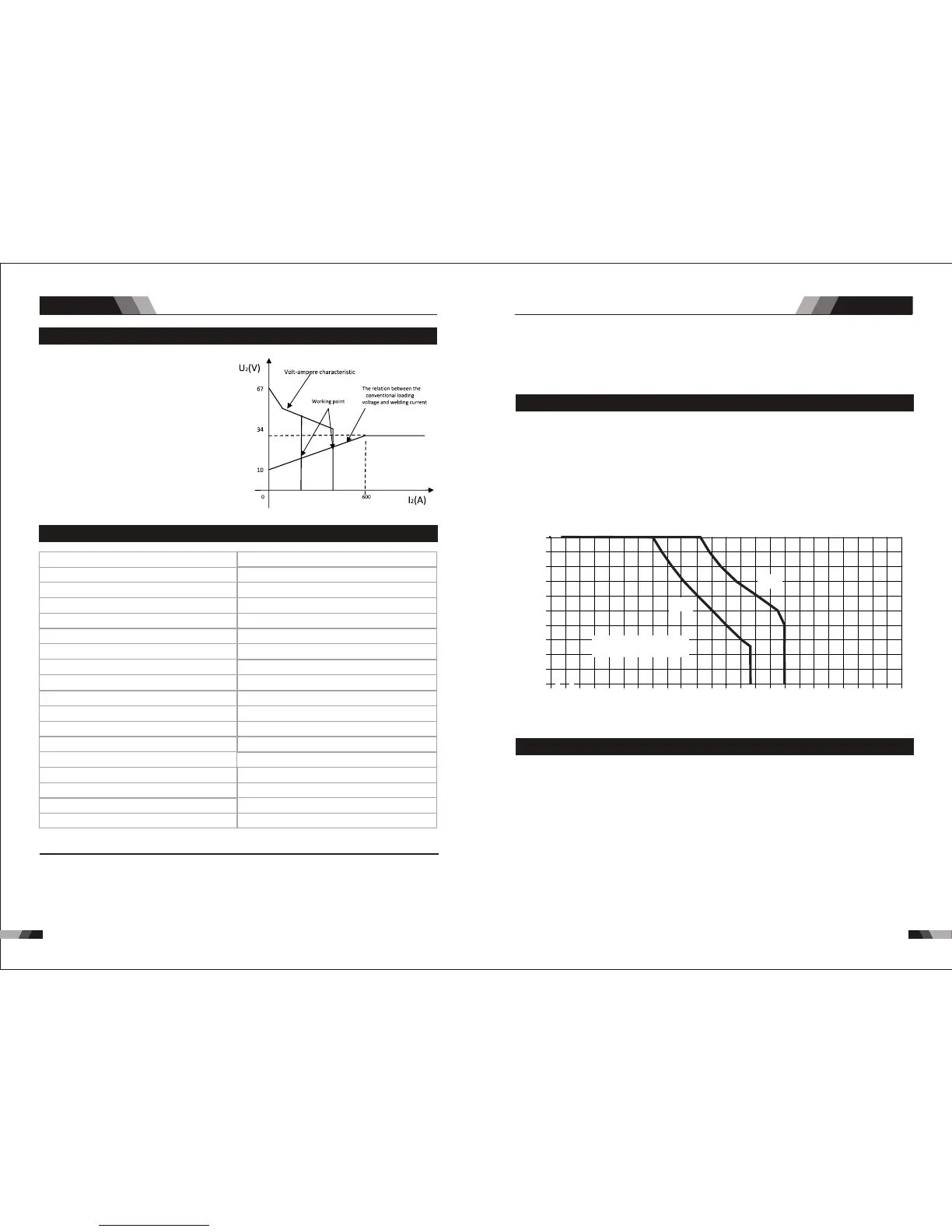
2.3 Volt- Ampere Characteristic
When I ≤600A, U =10+0.04I (V);
2 2 2
When I >600A,U =34(V).
2 2
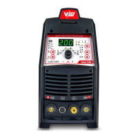
TIG London2400 AC/ DC welding
machine has an excellent volt-ampere
characteristic, whose graph is shown
as the following figure. The relation
between the conventional rated loa-
ding voltage U and the conventional
2
welding current I is as follows:
2
2.4 Specifications
170A @ 25%, 26.8V / 85A @ 100%, 23.4V
200A @ 40%, 18V / 126A @ 100%, 15V
9.88 kg
10 - 170A
10 - 200A
15.4A
30.9A
10KVA
H360mmxW160mmxD380mm
Description
Weight
Power Source Dimensions
Cooling
Welder Type
European Standards
Number of Phases
Nominal Supply Voltage
Nominal Supply Frequency
Welding Current Range (MMA Mode)
Welding Current Range (TIG Mode)
Single Phase Generator Requirement
MMA Welding Output, 40ºC, 10 min.
TIG Welding Output, 40ºC, 10 min.
Open circuit voltage (MMA/TIG)
Protection Class
Maximum Input Current
Effective Input Current
SIWM DIGITAL London2400
Fan Cooled
EN 60974-1 / IEC 60974-1
1
230V +/- 15%
50/60Hz
60V DC
IP23
Inverter Power Source
Note 3: Motor start fuses or thermal circuit breakers are recommended for this application.
Check local requirements for your situation in this regard.
Note 1: The Effective Input Current should be used for the determination of cable size &
supply requirements.
Note 2: Generator Requirements at the Maximum Output Duty Cycle.
NOTE
Due to variations that can occur in manufactured products, claimed performance, voltages,
ratings, all capacities, measurements, dimensions and weights quoted are approximate
only. Achievable capacities and ratings in use and operation will depend upon correct
installation, use, applications, maintenance and service.
2.5 Duty Cycle
The rated duty cycle of a Welding Power Source, is a statement of the time it may be
operated at its rated welding current output without exceeding the temperature limits of
the i ns ul ation of the co mp on ent parts. To exp la in the 10 minute duty cycle p er io d the
following example is used. Suppose a Welding Power Source is designed to operate at
a 5 0% duty cycle, 200 am pe re s at 2 8 vol ts . This means that it has been designed and
built to provid e the rat ed amperag e (200A) for 5 minu te s, i.e. arc weldi ng time, out of
every 10 minute period (50% of 10 minutes is 5 minutes). During the other 5 minutes of
the 10 minute per iod th e We lding Pow er Source must i dle and b e a llowe d to cool . Th e
thermal cut out will operate if the duty cycle is exceeded.
Duty Cycle(PERCENTAGE)
Welding Current(AMPS)
◆2.5m Power cable
◆200 Amp Electrode Holder With 2.5m cable
◆200 Amp Earth Clamp With 2.5m cable
◆4m TIG Torch WP-17
◆4m TIG Torch WP-17
◆3m Gas Hose
◆Operating Manual
2.6 Packaged Items
2525
5050
7575
100100 1 25125 150150 175175
00
1 01 0
2 02 0
3 03 0
4 04 0
5 05 0
6 06 0
7 07 0
8 08 0
9 09 0
1 0 01 0 0
2 00 225 250 27527500
Safe Operating Region
(TIG&STICK)
300
MMA
TIG
Summary
AC/DC WIG SERIES EQUIPMENTAC/DC WIG SERIES EQUIPMENT