18
19
Operation
Operation
3.4 Set-up For LIFT TIG (GTAW) Welding
WARNING
Before any welding is to begin, be sure to wear all
appropriate and recommended safety equipment.
4. Slowly open the Argon Cylinder Valve to the fully open position.
5. Connect the work lead clamp to your work piece.
6. The tungsten must be ground to a blunt point (similar to a pencil) in order to achieve
optimum welding results. See illustration. It is critical to grind the tungsten electrode
in the direction the grinding wheel is turning. Grind at a 30 degree angle and never
to a sharp point.
7. Install the tungsten with approximately 1.6mm to 3.2mm sticking out from the
gas cup, ensuring you have correct sized collet.
8. Tighten the back cap.
9. Turn the switch to the “ON” position. The power L.E.D. light should illuminate.
10. Set the welding process to LIFT TIG.
11. Set the Weld Current Control Knob to the desired amperage.
12. You are now ready to begin LIFT TIG Welding.
The following set up is known as Straight Polarity or DC electrode positive. This is
commonly used for DC LIFT TIG welding on most materials such as steel and stainless
steel.
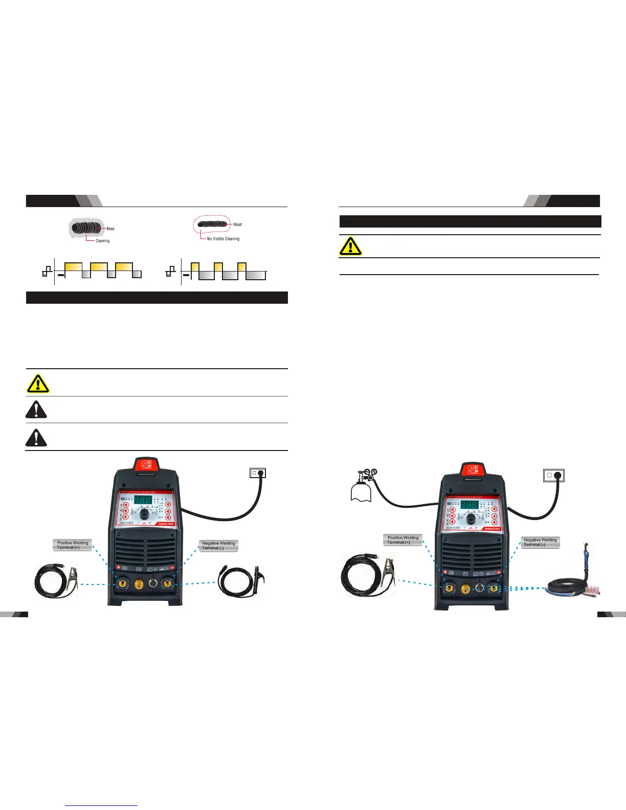
1. Switch the ON/OFF Switch (located on the rear panel) to OFF.
2. Connect the work lead cable to the positive output terminal, and the LIFT TIG Torch
cable to the negative output terminal.
3. Connect the gas line/hose to the proper shielding gas source.
NOTE
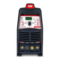
Ar./GAS(TIG/WIG)
power supply
Earth Clamp
TIG Torch
3.3 Setup For STICK (MMA) Welding
WARNING
Be f ore con n ect i ng t h e wo rk cl amp to t h e wo r k an d
inserting the ele ctro de in the electro de holder make
sure the mains power supply is switched off.
CAUTION
CAUTION
Remove any pa ckaging material prior to use. Do not
block the air vents at the front or rear of the Welding
Power Source.
Lo o se we ldi n g te rmi n al co nne c tio n s ca n ca u se
ove rheatin g and result in the mal e p lug being fused
in the bayonet terminal.
For Alkaline Electrode,connect the electrode holder to the positive welding termimal
Electrode,please connect the electrode holder to the negative welding termimal and
manufacturer. Welding current flows from the Power Source via heavy duty bayonet type
terminals. It is essential, however, that the male plug is inserted and turned securely to
achieve a sound electrical connection. Select STICK mode with the process selection
control.
a n d c o n n e c t t h e w o r k l e a d t o t h e n e g a t i v e w e l d i n g t e r m i n a l , w h i l e f o r t h e A c i d
con nect the wor k l ead to the positv e w eldin g t erminal .If in doub t c onsul t t he ele ctrode
Wider bead and cleaning action Narrower bead, with no visible cleaning
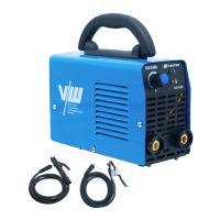
power supply
Earth Clamp
Electrode Holder
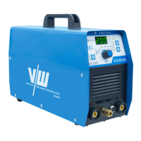
AC/DC WIG SERIES EQUIPMENTAC/DC WIG SERIES EQUIPMENT