Preparing The TLS-450 Console For Upgrade Removing The CPU Board
10
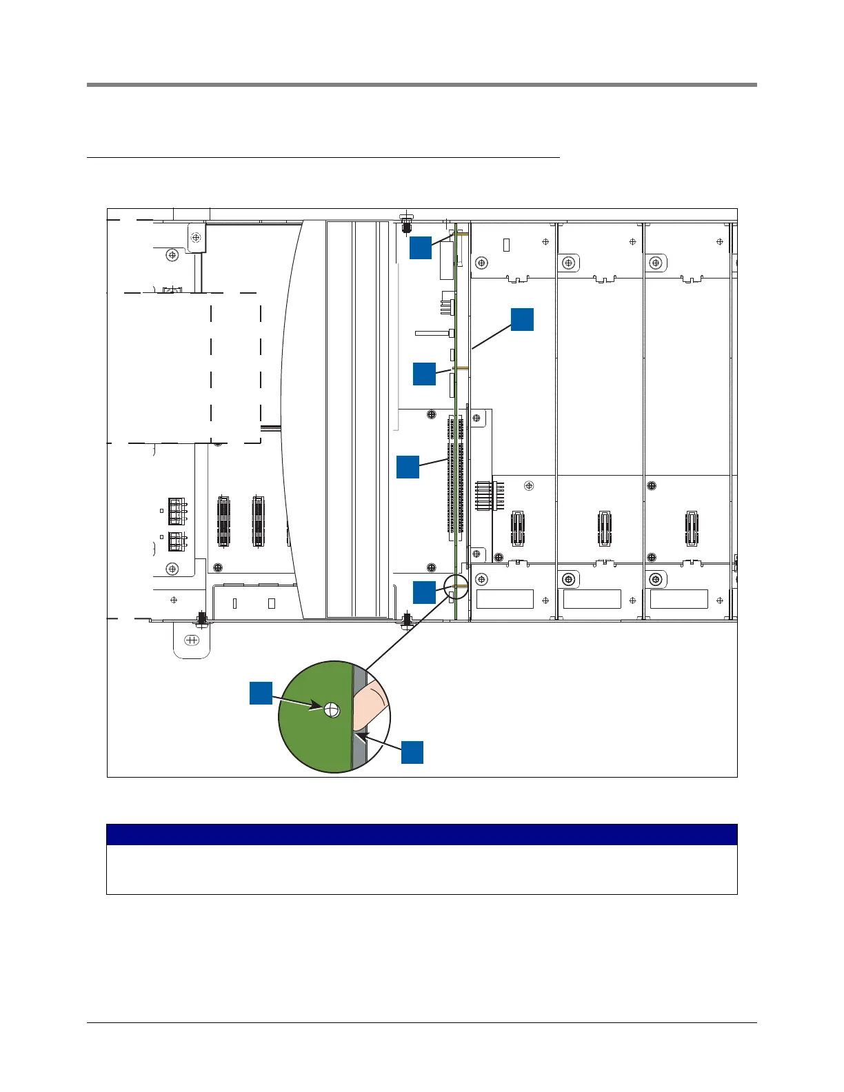
Removing The CPU Board
1. Locate the three retention snap pins along the front of the CPU board (see Figure 8).
Figure 8. Locating CPU Board Retention Snap-Pins
2. Remove the grounding wrist strap (Part No. 576010-908) from its package and wrap one end around your
wrist. Adhere the other end to a metal surface on the inside of the console.
3. Position your forefinger beneath one of the pins and press up releasing the CPU board from the snap pin
(see item 4 in Figure 8). Repeat at each of the remaining two retention pins.
LEGEND FOR NUMBERED BOXES IN Figure 8
1. Board retention snap pins
2. Compartment bulkhead.
3. CPU board backplane connector.
4. Use finger to pry board off snap pin.
RELAY RATINGSRELAY RATINGS
240 VAC, 2 A MAX240 VAC, 2 A MAX
24 VDC, 2 A MAX24 VDC, 2 A MAX
WARNING: TO MAINTAIN
INTRINSIC SAFETY, ALL
COVERS MUST BE IN
PLACE.
WARNING: TO MAINTAIN
INTRINSIC SAFETY, ALL
COVERS MUST BE IN
PLACE.
WARNING: TO MAINTAIN
INTRINSIC SAFETY, ALL
COVERS MUST BE IN
PLACE.
1
1
1
954-8.ep
2
3
4
1