13
Preparing The TLS-450 Console For Upgrade Comm Module Upgrades
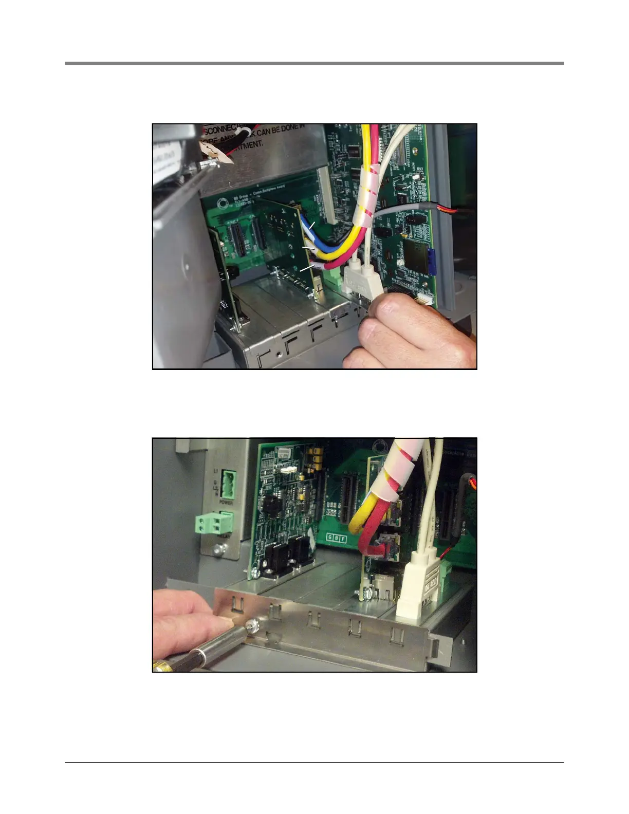
4. Install the TLS-450PLUS USB Module in slot 5 (see Figure 12).
Figure 12. Install USB/Wireless Module In Slot 5
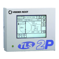
5. Relocate other Comm module(s) in available slot(s). If CDIM module was in slot 4 relocate it to slot 1 or 2.
Replace Comm module clamp and securing screw (see Figure 13).
Figure 13. Replace Comm Module Clamp And Securing Screw
blue
blue
yellow
yellow
red
red