15
Preparing The TLS-450 Console For Upgrade Installing New TLS-450PLUS CPU Board
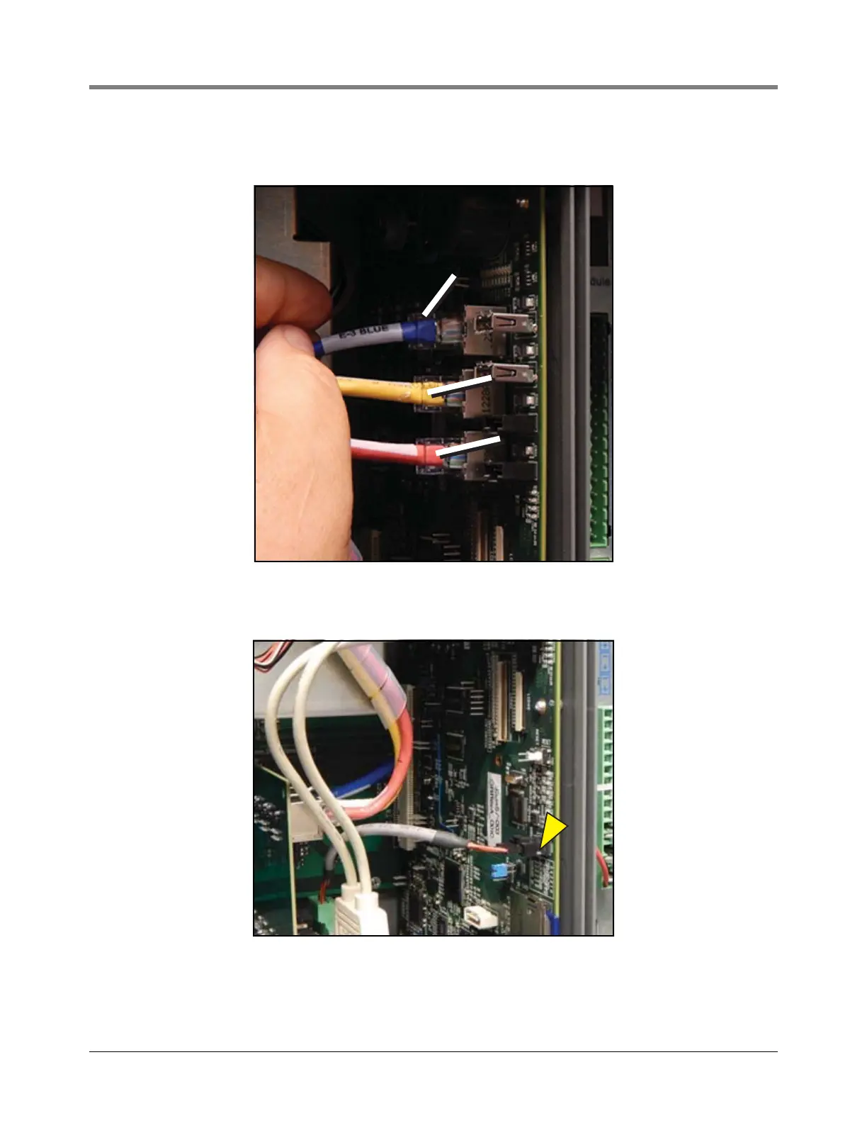
4. Reconnect the Ethernet Interface module’s three cables to the CPU board’s Ethernet connectors. Blue cable
(E 3) to top connector, yellow (E 2) to next down and red (E 1)to lower connector - see Figure 17).
Figure 17. Connect Ethernet Cables
5. Connect the Wireless cable to the CPU board (see Figure 18).
Figure 18. Connect Wireless Cable
6. Connect the two USB module USB cables (labeled 3 and 4) to the CPU board USB 3 and 4 connectors (see
Figure 19).
blue
blue
yellow
yellow
red
red