Preparing The TLS-450 Console For Upgrade Comm Module Upgrades
12
Comm Module Upgrades
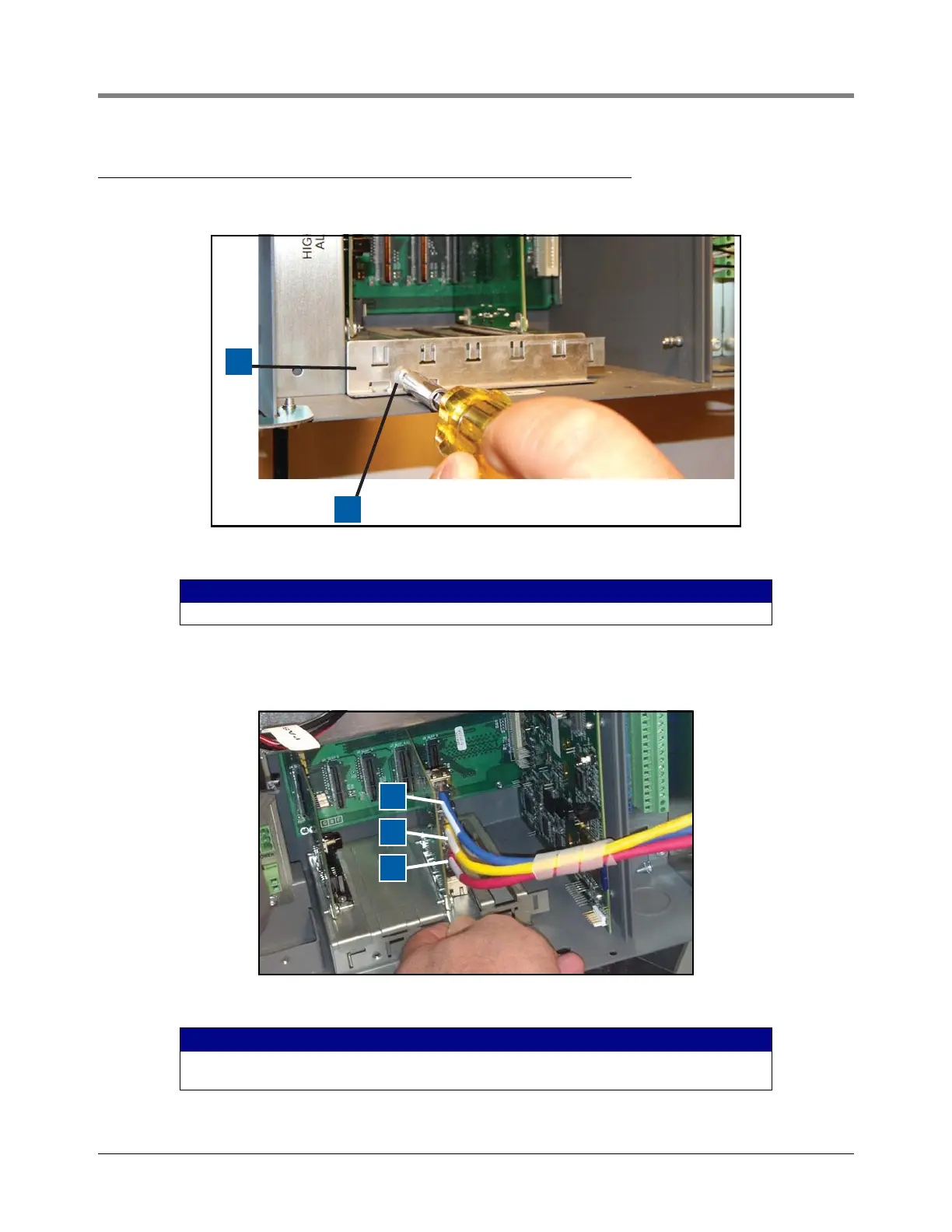
1. Remove the module clamp securing screw and set aside clamp and screw (see Figure 10).
Figure 10. Removing Comm Module Clamp
2. Remove Comm boards from Comm Module Bay slots 4 and 5 (see Figure 1) and set aside.
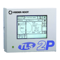
3. Install the TLS-450PLUS Ethernet Interface module in slot 4 (see Figure 11).
Figure 11. Install Ethernet Module In Slot 4
LEGEND FOR NUMBERED BOXES IN Figure 9
1. Comm module clamp 2. Clamp securing screw
LEGEND FOR NUMBERED BOXES IN Figure 9
1. Blue (E3)
2. Yellow (E2)
3. Red (E1)