Preparing The TLS-450 Console For Upgrade Removing The Display Door
8
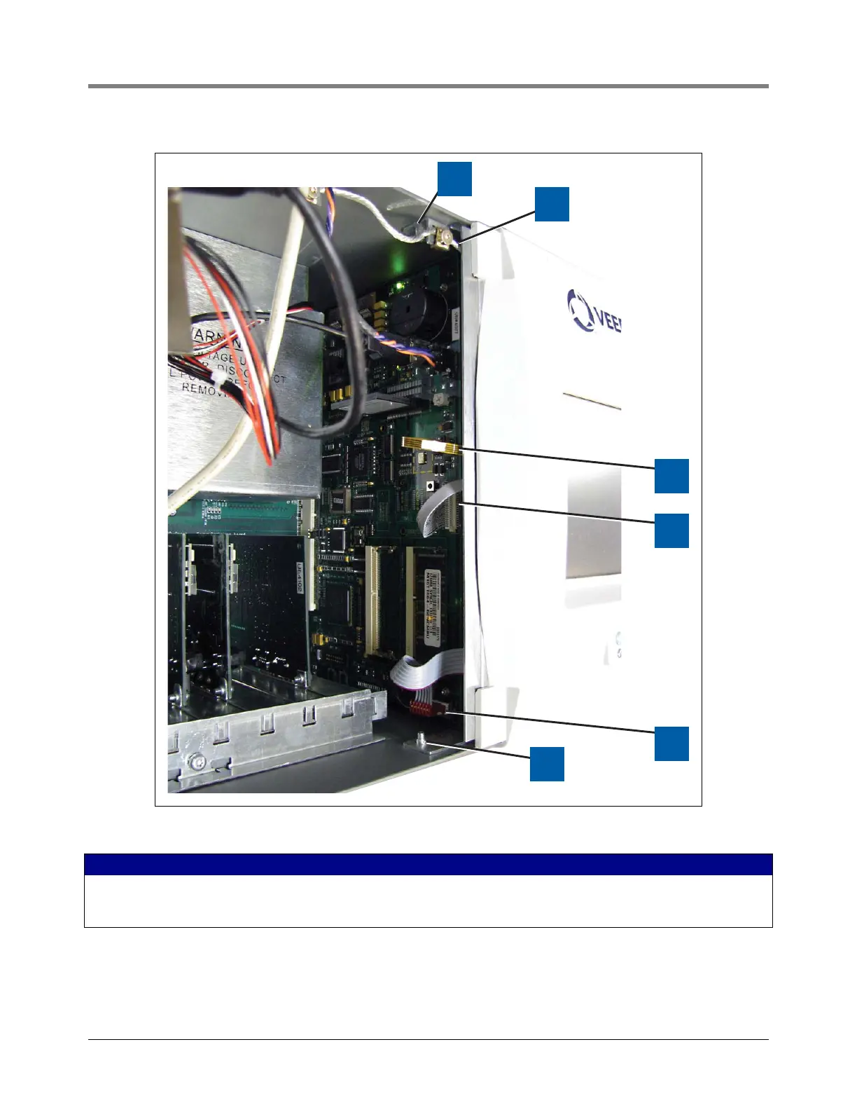
Figure 7. Removing The Three Display Panel Cables
LEGEND FOR NUMBERED BOXES IN Figure 7
1. Top Display door hinge shoulder screw
2. Grounding wire
3. Touchscreen control cable
4. Display data cable
5. LED/Display cable
6. Bottom Display door hinge shoulder screw