18
4 Connecting to power supply
FIBERTRAC 31 • Four-wire 4 … 20 mA/HART
62067-EN-211203
Inductive loads also result from the connection to a PLC input or
output and/or in combination with long cables. It is imperative that you
takemeasurestoextinguishsparkstoprotecttherelaycontact(e.g.Z
diode) or the transistor or 8/16 mA output.
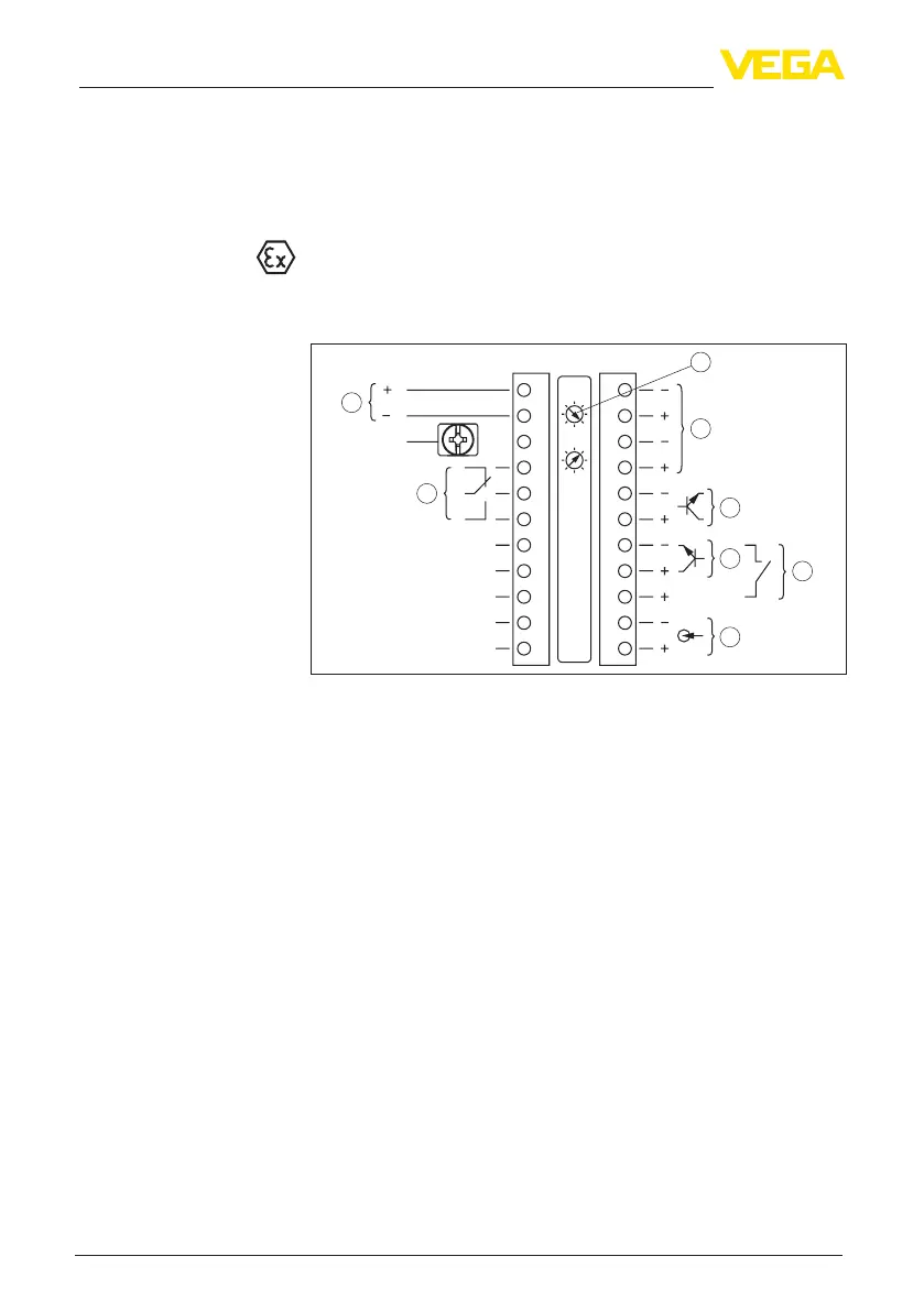
Instruments with intrinsically safe current output
Youcannddetailedinformationontheexplosion-protectedversions
(Ex-ia,Ex-d)intheEx-specicsafetyinstructions.Thesesafety
instructionsarepartofthescopeofdeliveryandcomewiththeEx-
approved instruments.
1
1
24
/L
/N
PE
56
22
11
12
2122 1920 18 17 14 1316 15 12
2
5
1
3
4
6
7
8
Fig. 14: Electronics and connection compartment (Ex-d) with instruments with
intrinsically safe current output
1 Voltage supply
2 Relay output
3 Signal input 4 … 20 mA
4 Switching input for NPN transistor
5 Switchinginputoating
6 Transistor output
7 Interface for sensor-sensor communication (MGC)
8 Setting the bus address for sensor-sensor communication (MGC)
4)
Electronics and connec-
tion compartment - In-
struments with intrinsi-
cally safe current output
4)
MGC = Multi Gauge Communication