21
5 Set up with the display and adjustment module
FIBERTRAC 31 • Four-wire 4 … 20 mA/HART
62067-EN-211203
5 Set up with the display and adjustment
module
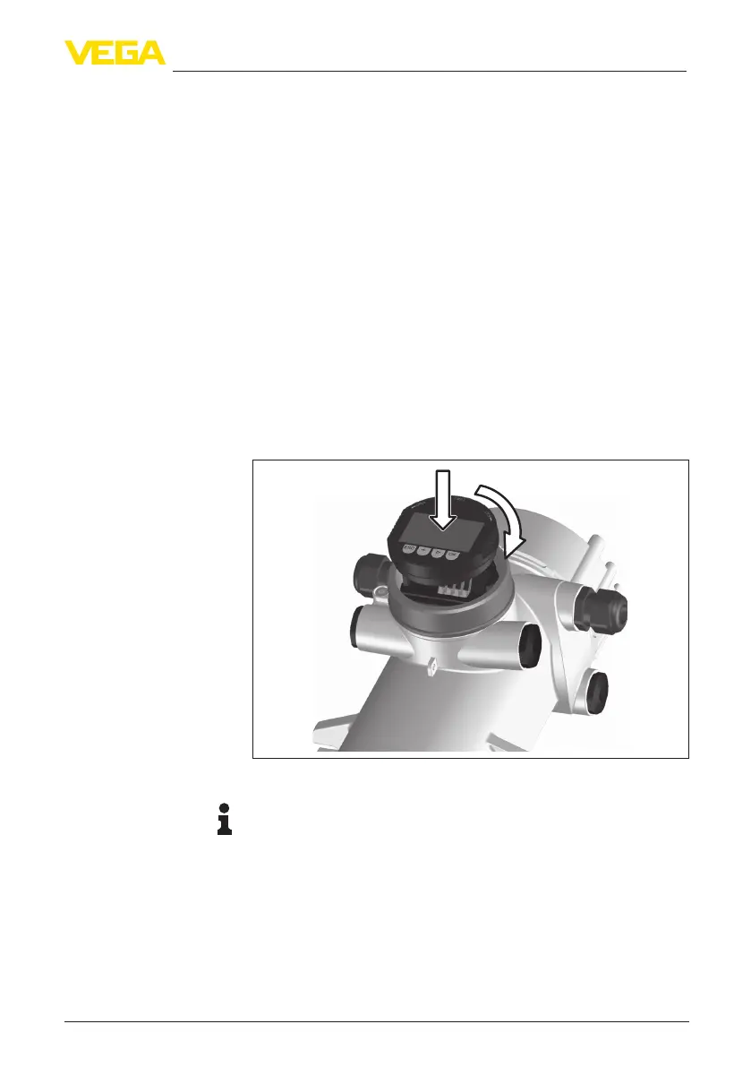
5.1 Insert display and adjustment module
The display and adjustment module can be inserted into the sensor
and removed again at any time. It is not necessary to interrupt the
voltage supply.
Proceed as follows:
1. Unscrew the small housing cover
2. Place the display and adjustment module in the desired position
ontheelectronics(youcanchooseanyoneoffourdierentposi-
tions - each displaced by 90°)
3. Press the display and adjustment module onto the electronics
and turn it to the right until it snaps in
4. Screw housing lid with inspection window tightly back on
Disassembly is carried out in reverse order.
Thedisplayandadjustmentmoduleispoweredbythesensor,anad-
ditional connection is not necessary.
1
2
Fig. 17: Insert display and adjustment module
Note:
Ifyouintendtoretrottheinstrumentwithadisplayandadjustment
moduleforcontinuousmeasuredvalueindication,ahigherlidwithan
inspection glass is required.
5.2 Parameter adjustment - Summation
Secondary
Tomeasurethelevelinveryhighvessels,multipleinstrumentscanbe
cascaded.
Mount/dismount display
and adjustment module
Cascading